Basic Circuit
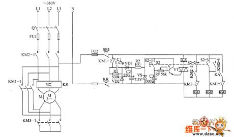
Motor decompression starter circuit diagram 2
Published:2011/5/21 23:32:00 Author:Lucas | Keyword: Motor decompression starter | From:SeekIC

Motor decompression starter is composed of the power supply circuit, the delay control circuit and control implementation circuit, the circuit is shown as the chart. Power supply circuit is composed of the fuses FU1, FU2, stop button S1, capacitors C1, C2, the normally closed contacts of thermal relay KR , resistors R1, R2 and Zener diode VS. Delay control circuit is composed of the start control button S2 (S2-1 ~ S2-3), capacitor C3, potentiometer RP, transistors V, VT and intermediate relay KA. Control implementation circuit is composed of AC contactors KM1 ~ KM3, linkage contacts S2-2, S2-3 of qo and the normally open contacts of KA. AC 220V voltage is bucked by C1, rectified by VD1, filtered by C2, limited by R2 and stabilized by VS to produce the 7.5V DC voltage, which is added to the collector of V. R1 and R2 select 1/4W metal film resistors. RP uses synthetic carbon potentiometer.
Reprinted Url Of This Article:
http://www.seekic.com/circuit_diagram/Basic_Circuit/Motor_decompression_starter_circuit_diagram_2.html
Print this Page | Comments | Reading(3)

Article Categories
power supply circuit
Amplifier Circuit
Basic Circuit
LED and Light Circuit
Sensor Circuit
Signal Processing
Electrical Equipment Circuit
Control Circuit
Remote Control Circuit
A/D-D/A Converter Circuit
Audio Circuit
Measuring and Test Circuit
Communication Circuit
Computer-Related Circuit
555 Circuit
Automotive Circuit
Repairing Circuit
Code: