Basic Circuit
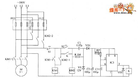
The motor dual insurance starter circuit diagram
Published:2011/5/21 0:58:00 Author:Lucas | Keyword: dual , insurance starter , motor | From:SeekIC

The motor dual insurance starter circuit is composed of the Road 1 fuse FU1, Road 2 fuse FU2, stop button R1, start button S2, AC contactors KM1, KM2, relay K, capacitors C1 ~ C3, diodes VD1, VD2, resistor R, voltage regulator diode VS, potentiometer RP and time-based integrated circuit IC, the circuit is shown as the chart. After people press the start button S2, KM2 pulls in and its normally open contacts KM2-i and KM2 ˉ 2 are connected, the motor M operates. At the same time, the AC voltage across L2, L3 is bucked by C1, stabilized by VS, filtered by VD1 and rectified by C2 to provide the +12 V power supply for IC. R uses 1W metal film resistor. RP selects small organic solid potentiometer or variable resistor. IC uses NE555 base integrated circuit.
Reprinted Url Of This Article:
http://www.seekic.com/circuit_diagram/Basic_Circuit/The_motor_dual_insurance_starter_circuit_diagram.html
Print this Page | Comments | Reading(3)

Article Categories
power supply circuit
Amplifier Circuit
Basic Circuit
LED and Light Circuit
Sensor Circuit
Signal Processing
Electrical Equipment Circuit
Control Circuit
Remote Control Circuit
A/D-D/A Converter Circuit
Audio Circuit
Measuring and Test Circuit
Communication Circuit
Computer-Related Circuit
555 Circuit
Automotive Circuit
Repairing Circuit
Code: