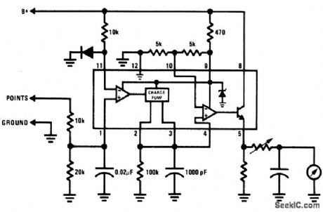
Circuit Diagram
Index 1338
WINDSHIELD_WIPER_CONTROL
Published:2009/6/24 4:22:00 Author:May

Here's a good way to set windshield wipers on an interval circuit. Only two connections to the car's wiper control, plus ground, are required. Variable control can be accomplished by substituting a 500 K pot in series with a100 K fixed resistor in place of the 560 K. (View)
View full Circuit Diagram | Comments | Reading(1024)
CAPACITOR_DISCHARGE_IGNITION_SYSTEM
Published:2009/6/24 4:22:00 Author:May
View full Circuit Diagram | Comments | Reading(0)
LM3911_TEMPERATURE_CONTROLLER
Published:2009/6/24 4:21:00 Author:May

The LM3911 requires only a few resistors and a capacitor to tum into a full-function tem-perature controller. The LM3911 requires very few external components to implement a full-function temperature controller. The figure illus-trates the sirnplicity of the freeze fighter circuit.The resistor network consisting of R1, R2, and R3 is used to provide the set point voltage for the feedback input of the LM3911.Resistor R4 limits the current through the in-ternal voltage reference of the LM3911 and can be selected from a wide range of values. 7.5 kQ is specified in most of the application notes.Resistor R5 pulls the output of the IC high when the temperature is below the set point. The internal resistor is in series with a diode that al-lows a switching voltage up to 35 V to be used with the device. (View)
View full Circuit Diagram | Comments | Reading(586)
BAR_GRAPH_ROOM_TEMPERATURE_DISPLAY
Published:2009/6/24 4:20:00 Author:May
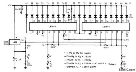
This display shows temperature as a bar graph. The range is 67°F to 86°F. (View)
View full Circuit Diagram | Comments | Reading(2093)
OPTOELECTRONIC_PYROMETER
Published:2009/6/24 4:19:00 Author:May

This setup optically measures the temperature of an incandescent body. It makes use of the shift in the emission spectrum of a black body toward shorter wavelengths, as temperature is increased.Optical ffiters are used to split the emission spectrum, with one photodiode being illuminated by short wavelengths (visible light) and the other by long (infrared). The photocurrents are converted to logarithms by Q1 and Q2. These are subtracted to generate an output that varies as the log of the ratio of the illumination irttensiftes. Thus, the circuit is sensitive to changes in spectral distribution, but not intensity. (View)
View full Circuit Diagram | Comments | Reading(0)
BREAKER_POINT_DWELL_METER
Published:2009/6/24 4:19:00 Author:May
View full Circuit Diagram | Comments | Reading(995)
DIFFERENTIAL_THERMOMETER
Published:2009/6/24 4:18:00 Author:May
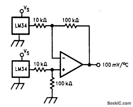
The differential thermometer shown in the figure produces an output voltage which is proportional to the temperature difference between two sensors. This is accomplished by using a dif-ference amplifier to subtract the sensor outputs from one another and then multiplying the differ-ence by a factor of 10 to provide a single-ended output of 100 mV per degree of differential tem-perature. (View)
View full Circuit Diagram | Comments | Reading(0)
NINE_BAND_SHORTWAVE_RECEIVER
Published:2009/6/24 4:18:00 Author:May

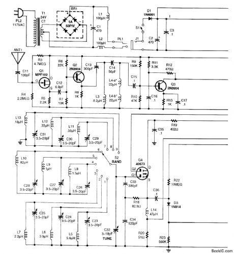
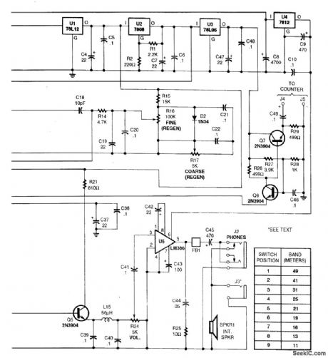
Dual-gate MOSFET Q4 is used as a regenerative amplifier in this circuit.An active antenna feeds the signal to Q4,and a short whip antenna is adequate.Derector Q5 feeds volume control R24,and audio amplifier U5,an LM386.The frequency is 49 to 11 meters in nine bands (6 to 27 MHz). (View)
View full Circuit Diagram | Comments | Reading(1589)
TEMPERATURE_TO_FREQUENCY_CONVERTER_KELVIN
Published:2009/6/24 4:17:00 Author:May

This simple connection results in a direct conversion of temperature to frequency. The 1-mV/°K temperature output serves as the input to the buffer amplifier, and the oscillator drive current is scaled to be 298μA at 298°K (+25℃). Use of a 1000-pF capacitor results in a corresponding fre-quency of 2.98 kHz. A single-point trim for calibration is normally sufficient to give errors less than ±2℃ from -55℃ to +125℃. An NPO capacitor is preferred to minimize nonlinearity that results from capacitance drift. (View)
View full Circuit Diagram | Comments | Reading(1483)
FREEZE_UP_SENSOR
Published:2009/6/24 4:31:00 Author:Jessie
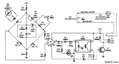
Using a bridge circuit to provide an accurate activation temperature, this circuit will turn on a heating unit or other device when the temperature drops below the trip point set by R2. Use a 10-kΩ resistor in place of the thermistor to calibrate it for 32'F activation. (View)
View full Circuit Diagram | Comments | Reading(991)
RELAY_INTERFACE_TO_RC_RECEIVERS
Published:2009/6/24 4:30:00 Author:Jessie
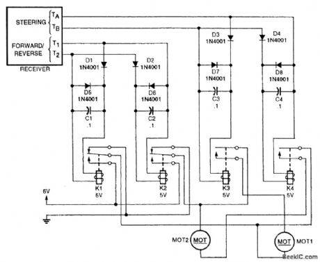
You can add relays to some inexpensive RC receivers to operate your own chassis. (View)
View full Circuit Diagram | Comments | Reading(586)
TEMPERATURE_TO_DIGITAL_OUTPUT_CONVERTER
Published:2009/6/24 4:30:00 Author:Jessie
View full Circuit Diagram | Comments | Reading(814)
TEMPERATURE_CONTROLLER_1
Published:2009/6/24 4:29:00 Author:Jessie
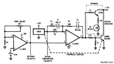
A proportional temperature controller can be made with an LM34 and a few additional parts. The complete circuit is shown. Here, an LM10 serves as both a temperature-setting device and as a driver for the heating unit (an LM395 power transistor). The optional lamp, driven by an LP395 transistor, is for indicating whether or not power is being applied to the heater. (View)
View full Circuit Diagram | Comments | Reading(1641)
TWO_CHIP_AM_RECEIVER
Published:2009/6/24 4:29:00 Author:Jessie
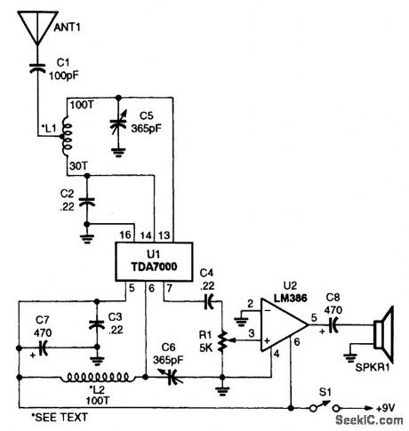
This receiver is comprised of a TDA7000 single-chip FM receiver (U1), an LM386 low-voltage audio-power amplifier (U2), a pair of hand-wound coils (L1 and L2), and a few additional components.L1 and L2 are 100 tums of #28 wire on toroidal cores (about 240 μH each). L1 is tapped at 30 turns. (View)
View full Circuit Diagram | Comments | Reading(2512)
THERMOSTATIC_RELAY_APPLICATION
Published:2009/6/24 4:28:00 Author:Jessie

K1, the thermostatic relay, energizes power relay K2, which handles the circuit's power switching. The drawing doesn't show K2's power-switching contacts. (View)
View full Circuit Diagram | Comments | Reading(886)
TEMPERATURE_DIFFERENTIAL_DETECTOR
Published:2009/6/24 4:28:00 Author:Jessie
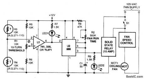
This circuit measures temperature differences, not temperature. Once the difference passes a certain threshold, the timer is triggered, activating the solid-state relay.Op amp U1 is placed in a comparator configuration with two thermistors-one located at the ceiling, one at the floor. The IC senses the temperature difference between the ceiling and floor, but is unaffected by the overall room temperature differential increases. The upper thermistor will de-crease in resistance, eventually causing the voltage at pin 2 of U1 to exceed that pin 2 of U1 to go low and trip the timer. This adds hysteresis to the op amp's output, preventing the motor from chatter-ing. When tripped, the timer activates the relay, which activates the fan. (View)
View full Circuit Diagram | Comments | Reading(3269)
VIDEO_LINE_RECEIVER
Published:2009/6/24 4:28:00 Author:Jessie
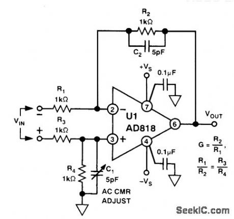
This circuit can achieve 46-dB common-mode rejection if R1, R2, R3, and R4 are matched to 1%. C1 is adjusted for best CMR above 1 MHz. (View)
View full Circuit Diagram | Comments | Reading(626)
THERMOCOUPLE_COLD_JUNCTION_COMPENSATION
Published:2009/6/24 4:27:00 Author:Jessie

A single-supply circuit is shown. R3 and R4 divide down the 10-mV/°K output of the LM329B and its associated voltage divider provide a voltage to buck out the 0℃ output of the LM335. To calibrate, adjust R1 so that V1 = αT, where cc is the Seebeck coefficient and T is the ambient temperature in degrees Kelvin. Then, adjust R2 so that V1 - V2 is equal to the thermocouple output voltage at the known ambient temperature. (View)
View full Circuit Diagram | Comments | Reading(1155)
SIMPLE_CRYSTAL_RADIO
Published:2009/6/24 4:27:00 Author:Jessie
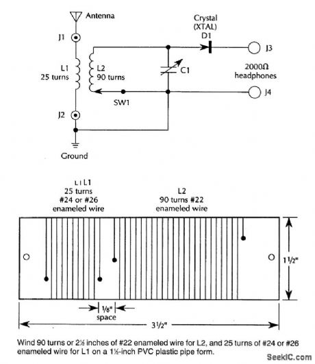
An IN34A (D1) is used as a detector in this crystal radio. A good outdoor antenna should be used. (View)
View full Circuit Diagram | Comments | Reading(2901)
TWO_BAND_RADIO
Published:2009/6/24 4:25:00 Author:Jessie
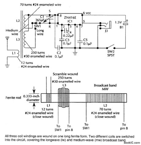
This TRF receiver covers the AM broadcast band and longwave bands (used in Europe and Asia for broadcasting). A loop antenna is used for reception and an extemal antenna can be connected.Frequency coverage is 150 to 1600 kHz. (View)
View full Circuit Diagram | Comments | Reading(3877)
| Pages:1338/2234 At 2013211322132313241325132613271328132913301331133213331334133513361337133813391340Under 20 |
Circuit Categories
power supply circuit
Amplifier Circuit
Basic Circuit
LED and Light Circuit
Sensor Circuit
Signal Processing
Electrical Equipment Circuit
Control Circuit
Remote Control Circuit
A/D-D/A Converter Circuit
Audio Circuit
Measuring and Test Circuit
Communication Circuit
Computer-Related Circuit
555 Circuit
Automotive Circuit
Repairing Circuit

