
Circuit Diagram
Index 1333
WIRELESS_GUITAR_TRANSMITTER
Published:2009/6/24 21:16:00 Author:Jessie

This transmitter has a built-in distortion effects unit and a touch switch to switch effects off and on. The circuit operates from a 9-V battery. IC1-a and IC1-b are used in the effects circuitry. IC1-d is an input preamp and IC2 is a quad analog switch to handle audio switching. Q1 acts as a varactor diode modulator while IC-4 is an 88- to 108-MHz FM oscillator. (View)
View full Circuit Diagram | Comments | Reading(2658)
LOW_FREQUENCY_RELAY_OSCILLATOR
Published:2009/6/24 5:42:00 Author:May

Depending on the value of C and the resistance of the relay coil, and the difference in pull-in and drop-out voltage, this circuit will oscillate at a low frequency. R limits in rush current to capacitor C to a level that the relay contacts can handle. Typically, for a 400-Ω relay, R can be 20 to 440 ohms.Flash rate is approximately 1 cycle/second, depending on the relay. (View)
View full Circuit Diagram | Comments | Reading(0)
SIMPLE_TOUCH_SWITCH
Published:2009/6/24 21:05:00 Author:May

Q2 is held cut off since Q1 normally is conducting. When the touch plate is contacted by a large object (human body, etc.), stray 60-Hz pickup is rectified by D1 and D2, and produces a negative voltage across R2-C2 and the gate of Q1. Q1 cuts off, causes Q2 to conduct, and the output goes low. (View)
View full Circuit Diagram | Comments | Reading(0)
VARIABLE_WIEN_BRIDGE_OSCILLATOR
Published:2009/6/24 21:15:00 Author:Jessie

This circuit uses a single potentiometer to tune a 300- to 3000-Hz range. A FET op amp is used at A1 and A2. The upper frequency limit is determined by the gain-bandwidth product of the op amps. (View)
View full Circuit Diagram | Comments | Reading(1065)
IONIZATION_CHAMBER_SMOKE_DETECTOR
Published:2009/6/24 21:15:00 Author:Jessie

Battery-operated, ionization chamber smoke detector includes a circuit to generate a unique alarm when the battery reaches the end of its useful life. The circuit uses the MCMOS MC14572 for two alarm oscillators (smoke and low battery). This circuit additionally uses five discrete transistors as buffers and comparators. (View)
View full Circuit Diagram | Comments | Reading(2221)
FAST_TURN_ON_DELAYED_OFF_RELAY_CIRCUIT
Published:2009/6/24 5:41:00 Author:Jessie

C is a large capacitor that has a charge time of RSUPPLY C, assuming RSUPPLY <Rcoil, The discharge time will be Rcoil C neglecting relay coil inductance. With C = 10,000 μF and Rcoil 500 Ω, a release time constant of 5 seconds might be obtained. Many relays will hold in until the coil current decays to 25% of the pull-in current so that the actual time constant depends on the relay holding current. (View)
View full Circuit Diagram | Comments | Reading(1145)
TRANSISTOR_RELAY_DRIVER
Published:2009/6/24 5:37:00 Author:Jessie

An input of 4 V or greater will drive this relay circuit. (View)
View full Circuit Diagram | Comments | Reading(1520)
LATCHING_RELAY_DRIVER
Published:2009/6/24 5:37:00 Author:Jessie

An input of 4 V or greater will drive this circuit. When the relay pulls in, one pair of contacts is used to latch the relay closed. It will remain closed until S1 is pressed. (View)
View full Circuit Diagram | Comments | Reading(1475)
FAST_TURN_ON_DELAYED_OFF_RELAY_CIRCUIT
Published:2009/6/24 5:41:00 Author:May
C is a large capacitor that has a charge time of RSUPPLY C, assuming RSUPPLY <Rcoil, The discharge time will be Rcoil C neglecting relay coil inductance. With C = 10,000 μF and Rcoil 500 Ω, a release time constant of 5 seconds might be obtained. Many relays will hold in until the coil current decays to 25% of the pull-in current so that the actual time constant depends on the relay holding current. (View)
View full Circuit Diagram | Comments | Reading(0)
HIGH_MPEDANCE_RELAY_DRIVER
Published:2009/6/24 5:35:00 Author:Jessie

A CMOS gate is used to drive a switching transistor and relay. (View)
View full Circuit Diagram | Comments | Reading(1020)
TRANSISTOR_RELAY_DRIVER
Published:2009/6/24 5:37:00 Author:May
An input of 4 V or greater will drive this relay circuit. (View)
View full Circuit Diagram | Comments | Reading(0)
LATCHING_RELAY_DRIVER_FOR+12_V_LOADS
Published:2009/6/24 5:33:00 Author:Jessie

A 4-V signal will cause the relay to pull in when Q1 turns on. Latching is obtained by feedback through a 4.7-kΩ resistor. A switch is used to select latching or nonlatching operation. A NO pushbutton releases the circuit. (View)
View full Circuit Diagram | Comments | Reading(1399)
LATCHING_RELAY_DRIVER
Published:2009/6/24 5:37:00 Author:May
An input of 4 V or greater will drive this circuit. When the relay pulls in, one pair of contacts is used to latch the relay closed. It will remain closed until S1 is pressed. (View)
View full Circuit Diagram | Comments | Reading(0)
HIGH_MPEDANCE_RELAY_DRIVER
Published:2009/6/24 5:35:00 Author:May
A CMOS gate is used to drive a switching transistor and relay. (View)
View full Circuit Diagram | Comments | Reading(0)
LATCHING_RELAY_DRIVER_FOR+12_V_LOADS
Published:2009/6/24 5:33:00 Author:May
A 4-V signal will cause the relay to pull in when Q1 turns on. Latching is obtained by feedback through a 4.7-kΩ resistor. A switch is used to select latching or nonlatching operation. A NO pushbutton releases the circuit. (View)
View full Circuit Diagram | Comments | Reading(0)
TWO_STAGE_TRF_REGENERATIVE_RECEIVER
Published:2009/6/24 4:51:00 Author:May

This regenerative receiver uses a tuned RE stage to improve performance. The coil in Fig. 76-24D is for the purpose of adding a second regenerative stage (RF amp). This coil is L5 in the schematic. (View)
View full Circuit Diagram | Comments | Reading(4697)
SIGNAL_TRACER
Published:2009/6/24 21:13:00 Author:Jessie

This circuit uses a simple detector-audio am-plifier. The output can be connected to head-phones or another audio amplifier. (View)
View full Circuit Diagram | Comments | Reading(2704)
ONE_TUBE_AM_RECEIVER
Published:2009/6/24 4:33:00 Author:May
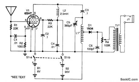
This radio uses an untuned RF stage to boost the signal voltage up to the linear portion of the crystal diode's characteristic curve. The circuit's distortion and wide bandpass and a good-quality transformer make for a great-sounding AM radio. L1 is a winding of #22 enamelled wire 2 long on a 2 diameter plastic pipe. T1 is a tube-type radio output transformer, rated at 2000 Ω to the speaker voice coil. (View)
View full Circuit Diagram | Comments | Reading(2127)
GAS_AND_SMOKE_DETECTOR
Published:2009/6/24 21:13:00 Author:Jessie
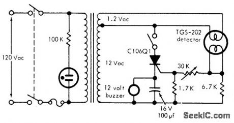
This circuit can detect smoke and a number of gases (CO, CO2, methane, coal gas and others) with a 10 ppm sensitivity. It uses a heated surface semiconductor sensor. Detection occurs when the gas concentration in-crease causes a decrease of the sensor element internal resistance. The switch in series with the SCR is used for resetting the alarm. (View)
View full Circuit Diagram | Comments | Reading(1695)
CABLE_TRACER
Published:2009/6/24 21:12:00 Author:Jessie

This circuit generates a 1-kHz square wave for cable tracing. Because this circuit is simple and generates from 1.5 V, several can be used at the same time to generate multiple tones for tracing multiconductor cables. (View)
View full Circuit Diagram | Comments | Reading(2142)
| Pages:1333/2234 At 2013211322132313241325132613271328132913301331133213331334133513361337133813391340Under 20 |
Circuit Categories
power supply circuit
Amplifier Circuit
Basic Circuit
LED and Light Circuit
Sensor Circuit
Signal Processing
Electrical Equipment Circuit
Control Circuit
Remote Control Circuit
A/D-D/A Converter Circuit
Audio Circuit
Measuring and Test Circuit
Communication Circuit
Computer-Related Circuit
555 Circuit
Automotive Circuit
Repairing Circuit