
Circuit Diagram
Index 1339
ONE_TUBE_REGENERATIVE_AM_RECEIVER
Published:2009/6/24 4:24:00 Author:Jessie
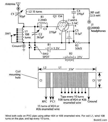
Suitable for AM reception and as a simple radio project, this circuit uses a single tube as a regenerative detector. (View)
View full Circuit Diagram | Comments | Reading(3781)
TEMPERATURE_TO_FREQUENCY_CONVERTER_CELSIUS
Published:2009/6/24 4:17:00 Author:May
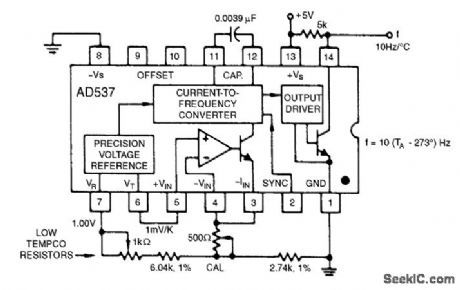
The 1.00-V reference output can be combined with the 1-mV/°K output to realize various temperature scales. For the Celsius scale, the lower end of the timing resistor must be offset by 273 mV. This is easily accomplished, and it results in an output from 0 to 1 kHz for temperatures from 0℃ to +100℃. Other offsets and scale factors are equally easy to implement. (View)
View full Circuit Diagram | Comments | Reading(0)
AF_POWER_OSCILLATOR
Published:2009/6/24 4:15:00 Author:May

An LM386 audio power IC is set up as a feedback oscillator. Any supply from 6 to 12 V can be used. The circuit can drive a loudspeaker. (View)
View full Circuit Diagram | Comments | Reading(0)
BASIC_FAHRENHEIT_TEMPERATURE_SENSOR
Published:2009/6/24 4:14:00 Author:May

View full Circuit Diagram | Comments | Reading(0)
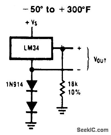
SINGLE_SUPPLY_TEMPERATURE_SENSOR(_50_TO__300°F)
Published:2009/6/24 4:14:00 Author:May
View full Circuit Diagram | Comments | Reading(0)
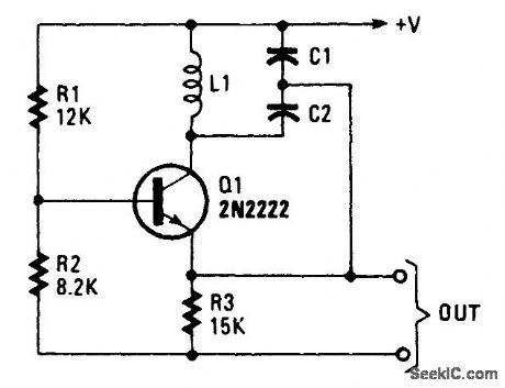
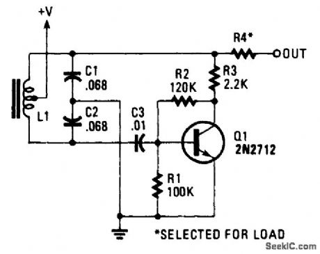
SIMPLE_RF_TEST_OSCILLATOR
Published:2009/6/24 4:13:00 Author:May

A simple oscillator for IF alignment (455 kHz) can prove useful in field testing or where a stan-dard signal generator is available. L1 should res-onate at the desired output frequency with the series combination of C2 and C3. (View)
View full Circuit Diagram | Comments | Reading(1389)
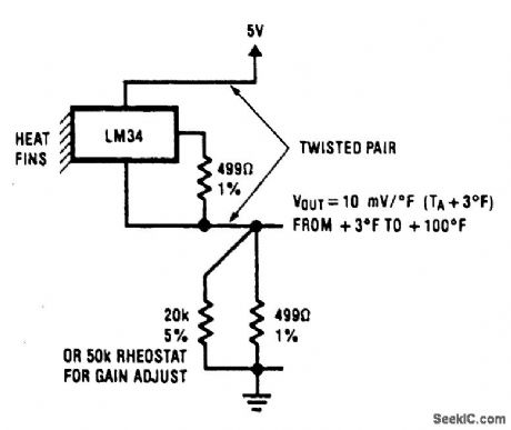
TWO_WIRE_TEMPERATURE_SENSOR_OUTPUT_REFERENCED_TO_GROUND
Published:2009/6/24 4:12:00 Author:May
View full Circuit Diagram | Comments | Reading(934)
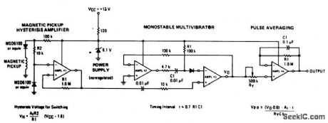
HIGH_SPEED_WARNING_DEVICE
Published:2009/6/24 4:11:00 Author:May

Al amplifies and regulates the signal from the spark coil. A2 converts frequency to vol-tage so that its output is a voltage proportional to engine rpm. A3 compares the tachometer voltage with the reference voltage and turns on the output transistor at the set speed. Amplifier A4 is used to generate an audible tone whenever the set speed is exceeded. (View)
View full Circuit Diagram | Comments | Reading(1340)
15_V_ELECTRONIC_THERMOMETER
Published:2009/6/24 4:11:00 Author:May
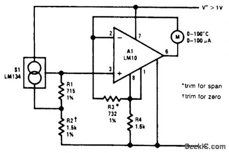
An electronic thermometer design, useful in the range of -55℃ to 150'℃, is shown. The sensor, S1, develops a current that is proportional to absolute temperature. This is given the required offset and range expansion by the reference and op amp, resulting in a direct readout in either ℃ or °F. (View)
View full Circuit Diagram | Comments | Reading(549)
CENTIGRADE_THERMOMETER_WITH_COLD_JUNCTION_COMPENSATION
Published:2009/6/24 4:10:00 Author:May
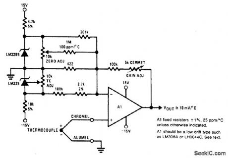
This electronic thermometer has a 10-mV/'C output from 0'C to 1300'℃. The trimming proce-dure is as follows: first short out the LM329B, the LM335 and the thermocouple. Measure the output voltage (equal to the input offset voltage times the voltage gain). Then apply a 50-mV input voltage and adjust the GAIN ADJUST pot until the output voltage is 12.25 V above the previously measured value. Next, short out the thermocouple again and remove the short across the LM335. Adjust the TC ADJUST pot so that the output equals 10 mV/°K times the absolute temperature. Finally, remove the short across the LM329B and adjust the ZER0 ADJUST pot so that the output voltage equals 10 mV/℃ times the ambient temperature in ℃. (View)
View full Circuit Diagram | Comments | Reading(0)
MOSFET_MXER_OSCILLATOR_CIRCUIT_FOR_AM_RECEIVERS
Published:2009/6/24 4:10:00 Author:May
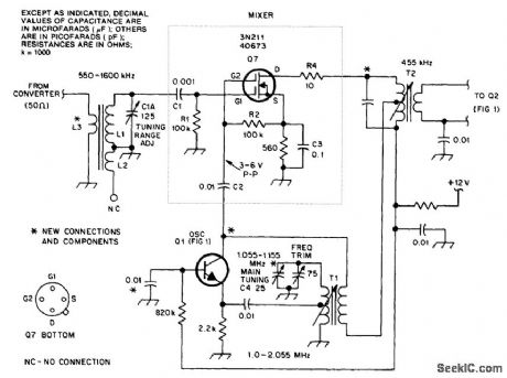
This circuit is an improved front end for upgrading a transistor AM receiver. This front end is useful when the radio is to be used as a tuneable IF amplifier with shortwave converters. (View)
View full Circuit Diagram | Comments | Reading(1809)
TACHOMETER_1
Published:2009/6/24 4:21:00 Author:Jessie
View full Circuit Diagram | Comments | Reading(485)
BAR_GRAPH_ROOM_TEMPERATURE_DISPLAY
Published:2009/6/24 4:20:00 Author:Jessie
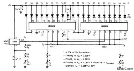
This display shows temperature as a bar graph. The range is 67°F to 86°F. (View)
View full Circuit Diagram | Comments | Reading(0)
BARGRAPH_CAR_VOLTMETER
Published:2009/6/24 4:08:00 Author:May

The LM3914 acts as a LED-driving vol-tometer that has its basic maximum and minimum readings determined by the values of R2 and RV2. When correctly adjusted, the unit actually covers the 2.5 volt to 3.6 volt range, but it is made to read a supply voltage span of 10-10.5 volts to 15 volts by interposing poten-tial divider R1-RV1 between the supply line and the pin-5 input terminal of the IC. The IC is configured to give a 'dot' display, in which only one of the ten LEDs is illuminated at any given time. If the supply voltage is below 10.5 volts none of the LEDs illuminate. Ifthe supply equals or exceeds 15 volts, LED 10 illuminates. (View)
View full Circuit Diagram | Comments | Reading(5402)
ABSOLUTE_TEMPERATURE_LOG_WITH_RS_232
Published:2009/6/24 4:08:00 Author:May
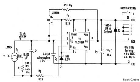
In the setup, T1 (an LM334 temperature sensor) generates a constant current that's propor-tional to absolute temperature, and equal to 25μA at 323 Kelvin (50℃). RI sets this constant of pro-portionality. The current discharges the parallel combination of C1 and C2 connected to the trigger and the threshold pins of UI, which is a CMOS implementation of the venerable 555 analog timer.The negative-going ramp is compared by UI to an internal2.S-V trigger level controlled by 21. When the ramp gets there, U1 triggers. The output pin (3) will go high, presenting a start bit to the con-nected communications port, which causes Q1 to source 100 μA to the timing node. At the same time, the discharge pin (7) will open, allowing R2 and the bottom end of C1 and T1 to be supplied by C1, and isolates it from C2.
Consequently, the current supplied by transistor Q1 will go solely to C2 so that when the result-ing positive-going ramp reaches 5V, exactly 25nC (2.5 V x C2) will have been deposited in the tim-ing node by the recharge cycle because its threshold level (6) will have been reached. This causes both the output pin to return to the negative rail, restoring the marking condition of the R2-232 in-terface, and Q1 to stop recharging C2. U1's discharge pin (7) now connects R2 to the negative rail, causing the charge that was deposited by T1 on C1 during the recharge interval to rapidly redistrib-ute between C1 and C2. This arrangement creates a very linear (0.01%) relationship between T1 cur-rent and pulse output frequency.
While this is happening, the PC's communications port hardware assembles a valid (although meaningless) character because the positive pulse output by UI looks like the start bit of a charac-ter. A simple program running in the PC can then count the frequency of these characters and con-vert the resulting rate into a direct readout of temperature. Because of the 3.1-Hz/degree slope of frequency versus temperature, a 30-second average suffices for 0.01°resolution. (View)
View full Circuit Diagram | Comments | Reading(0)
OPTOELECTRONIC_PYROMETER
Published:2009/6/24 4:19:00 Author:Jessie

This setup optically measures the temperature of an incandescent body. It makes use of the shift in the emission spectrum of a black body toward shorter wavelengths, as temperature is increased.Optical ffiters are used to split the emission spectrum, with one photodiode being illuminated by short wavelengths (visible light) and the other by long (infrared). The photocurrents are converted to logarithms by Q1 and Q2. These are subtracted to generate an output that varies as the log of the ratio of the illumination irttensiftes. Thus, the circuit is sensitive to changes in spectral distribution, but not intensity. (View)
View full Circuit Diagram | Comments | Reading(1833)
COLPITTS_OSCILLATOR
Published:2009/6/24 4:07:00 Author:May
View full Circuit Diagram | Comments | Reading(0)
LC_AUDIO_OSCILLATOR
Published:2009/6/24 4:06:00 Author:May
View full Circuit Diagram | Comments | Reading(0)
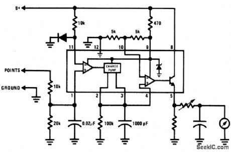
BREAKER_POINT_DWELL_METER
Published:2009/6/24 4:19:00 Author:Jessie
View full Circuit Diagram | Comments | Reading(0)
NE602_LOCAL_OSCILLATOR_CIRCUITS
Published:2009/6/24 4:05:00 Author:May
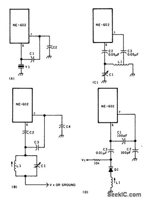
Local oscillator circuits for the NE602. (View)
View full Circuit Diagram | Comments | Reading(0)
| Pages:1339/2234 At 2013211322132313241325132613271328132913301331133213331334133513361337133813391340Under 20 |
Circuit Categories
power supply circuit
Amplifier Circuit
Basic Circuit
LED and Light Circuit
Sensor Circuit
Signal Processing
Electrical Equipment Circuit
Control Circuit
Remote Control Circuit
A/D-D/A Converter Circuit
Audio Circuit
Measuring and Test Circuit
Communication Circuit
Computer-Related Circuit
555 Circuit
Automotive Circuit
Repairing Circuit