
Circuit Diagram
Index 1323
10_GHz_WAVEGUIDE_DETECTOR_FOR_AMATEUR_RADIO_USE
Published:2009/6/24 22:31:00 Author:May
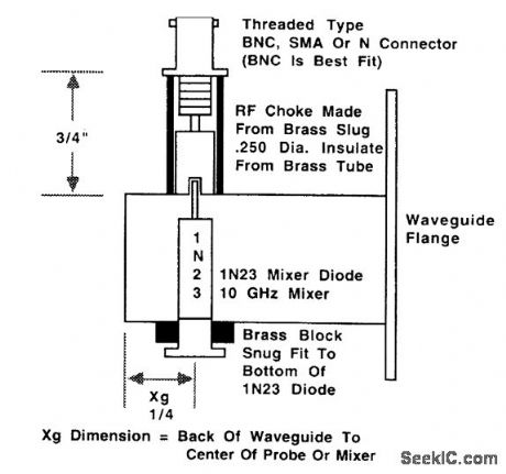
This shows the construction of a waveguide detector for use at the 10-GHz amateur radio fre-quencies. (View)
View full Circuit Diagram | Comments | Reading(951)
UNDERVOLTAGE_INDICATOR_FORBATTERY_OPERATED_EQUIPMENT
Published:2009/6/24 22:30:00 Author:May

Due to the low duty cycle of flashing LED, the average current drain is 1 mA or less. The NE555 will trigger the LED on when the moni-tored voltage falls to 12 volts. The ratio of R1 to R2 only needs to be changed if it is desired to change the voltage point at which the LED is triggered. (View)
View full Circuit Diagram | Comments | Reading(722)
FOUR_QUADRANT_PHOTO_CONDUCTIVE_DETECTOR_AMPLIFIER
Published:2009/6/24 22:30:00 Author:May
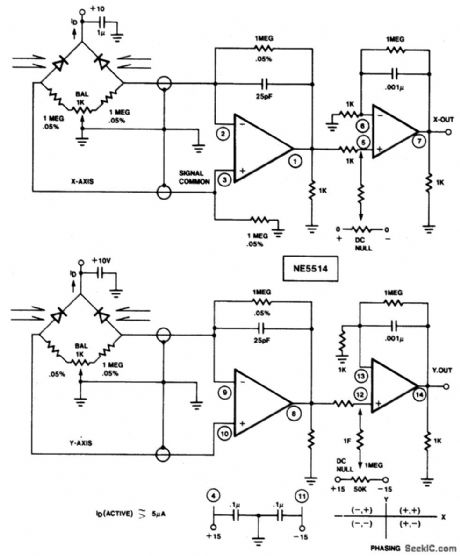
Use this circuit to sense four quadrant motion of a light source. By proper summing of the signals from the X and Y axes, four quadrant output may be fed to an X-Y plotter, oscilloscope, or computer for simulation. IC = NE/SE5514 (View)
View full Circuit Diagram | Comments | Reading(1506)
LOW_VOLTAGE_MONITOR
Published:2009/6/24 22:29:00 Author:May
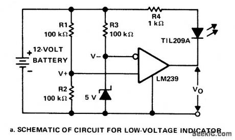
This circuit monitors the voltage of a battery and warns the operator when the battery voltage is below a preset level by turning on an LED. The values are set for a 12V automobile battery. The preset value is 10 volts. (View)
View full Circuit Diagram | Comments | Reading(930)
PRECISION_BATTERY_VOLTAGE_MONITOR_FOR_HTS
Published:2009/6/24 22:29:00 Author:May

The precision voltage-monitor chip con-tains a temperature -compensated voltage ref-erence. R1 divides down the battery voltage to match the built-in reference voltage of IC1 (1.15 volts). When the voltage at pin 3 falls below 1.15 volts, pin 4 supplies a constant current of 7 mA to drive a small LED. About 0.2 LED) volt of hysteresis is added with R2. Without hysteresis, the LED could flicker on and off when the monitored voltage varies around the set point, as might be the case on voice peaks during receive. (View)
View full Circuit Diagram | Comments | Reading(661)
OPTICAL_COMMUNICATION_SYSTEM
Published:2009/6/24 22:28:00 Author:May

The simple modulator stage will accommodate most common LEDs. By adjusting the potentiometer, the bias ofthe transistor is varied until the LED is at its half output point.Then, audio will cause it to vary above and below this point. The purpose of R1 is to limit the current through the LED to a safe level and the purpose of the 10 ohm resistor is to allow a portion of the modulating signal to be observed on a scope. (View)
View full Circuit Diagram | Comments | Reading(0)
SIMPLE_TEST_SIGNAL_GENERATOR
Published:2009/6/24 22:28:00 Author:May
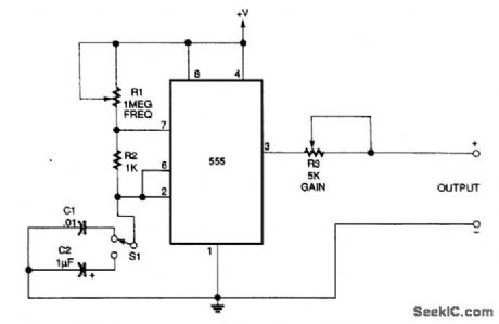
An NE555 generates signals for test purposes. Frequency range is from 20Hz to 10kHz, depending on the setting of S1. +Vis 5 V. (View)
View full Circuit Diagram | Comments | Reading(667)
ULTRASONIC_PEST_REPELLER
Published:2009/6/24 22:28:00 Author:May


This circuit uses two transistors and one IC (555 timer IC) to produce a pulsating ultrasonic frequency. Transistors Q1 and Q2 are connected in a direct-coupled oscillator. The frequency of that oscillator is set by capacitor C1. The oscillator output is taken from the emitter of Q2 to pin 7 of IC1. Transistor Q1 is an npn transistor, and Q2 is a pnp transistor. The signal of pin 7 on IC1 causes the output signal appearing ot) pin 3 to be modulated or varied by the audio frequency developed by Q1 and Q2. The IC itself is connected as a stable multivibrator with a frequency that is determined by C3. Capacitor C3 sets the basic frequency to be well above the human hearing range (ultrasonic). The combined modulated ultrasonic frequency appears on pin 3 of IC1, where it is coupled by capacitor C4 to the piezoelectric transducer. (View)
View full Circuit Diagram | Comments | Reading(0)
SIGNAL_SOURCE_FOR_AUDIO_AMPLIFIER_INVERTER
Published:2009/6/24 22:28:00 Author:May

Two op amps (741, etc..) are used in this oscillator circuit. A square wave is available and a sine wave, obtained by shaping the triangle waveform, is also provided. (View)
View full Circuit Diagram | Comments | Reading(984)
BATTERY_CHARGE_DISCHARGE_INDICATOR
Published:2009/6/24 22:28:00 Author:May

This circuit monitors car battery voltage. and yellow/green LEDs are on or off. For It provides an indication of nominal supply vol- example the red LED comes on at 11V, and the tage as well as low or high voltage. RV1 and green LED at 12V. The yellow LED is on RV2 adjust the point at which the red/yellow between these values. (View)
View full Circuit Diagram | Comments | Reading(1357)
PULSE_GENERATION_BY_INTERRUPTING_A_LIGHT_BEAM
Published:2009/6/24 22:27:00 Author:May
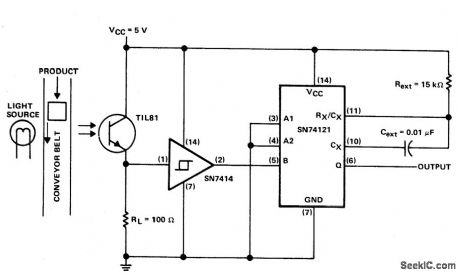
This circuit puts out a pulse when an object on the conveyor belt blocks the light source. The light source keeps the phototran-istor turned on. This produces a high-logic-level voltage at the Schmitt-trigger inverter and a TTL-compatible low logic level at pin 5 of the monostable. When an object blocks the light, TIL81 turns off the Schmitt-trigger inverter to triggers the one shot. (View)
View full Circuit Diagram | Comments | Reading(2340)
EQUIPMENT_ON_REMINDER
Published:2009/6/24 22:26:00 Author:May

Due to the low duty cycle of flashing LED, the average current drain is 1 mA or less. (View)
View full Circuit Diagram | Comments | Reading(595)
DIGITAL_SINE_WAVE_GENERATOR
Published:2009/6/24 22:26:00 Author:May

The sine-wave generator starts with an 8-MHz signal and divides it by eight to obtain 1 MHz at C1 (IC1's 2-MHz and 500-kHz outputs can serve as alternate drive signals). Qllevel-shifts the 1-MHz pulses so that they can drive the bipolar circuitry necessary for producing a bipolar output. Syn-chronous counter IC2 divides 1 MHz by 256 to give the desired output frequency (3906 Hz), and IC3 filters the harmonic frequencies.The filter's clock is taken from the first divide-by-2 tap of IC2 to assure a 50% duty cycle. IC2 fur-ther divides this signal by 128 to ensure that the filter's input signal (1 MHz/256) falls within the flat portion of the filter response.The output of the switched-capacitor filter resembles a sampled sine wave. It can be smoothed by building a first- or second-order low-pass filter around the otherwise uncommitted output op amp. (View)
View full Circuit Diagram | Comments | Reading(2822)
BATTERY_CONDITION_INDICATOR
Published:2009/6/24 22:26:00 Author:May

A 741 op amp is employed as a voltage comparator. The noninverting input is con-nected to zener reference source. Reference voltage is 5.IV. R2 is adjusted so that the vol-tage at the inverting input is half the supply voltage. When supply is higher than 10.2V, the LED will not light. When the supply falls just fractionally below the 10.2V level, the IC in-verting input will be slightly negative of the noninverting input, and the output will swing fully positive. The LED will light, indicating that the supply voltage has fallen to the preset threshold level. The LED can be made to light at other voltages by adjusting R2. (View)
View full Circuit Diagram | Comments | Reading(933)
PEST_REPELLER
Published:2009/6/24 22:25:00 Author:May

The two timers in the bug repeller have some interesting characteristics. Both of them have their thresholds externally set; the oscillator on the left has a 50% duty cycle and the oscillator on the right acts as a VCO. (View)
View full Circuit Diagram | Comments | Reading(968)
OP_AMP_SAWTOOTH_GENERATOR
Published:2009/6/24 22:25:00 Author:May

The sawtooth generator circuit shown is reset at the end of each cycle. The result is a constant peak-to-peak output throughout the circuit's frequency range.The constant-current generator circuit, the voltage-follower circuit, and the comparator circuit produce the waveform. A 555 timer IC (U2) is configured as a one-shot multivibrator that's triggered by the comparator's negative output pulse. (View)
View full Circuit Diagram | Comments | Reading(2221)
NI_CAD_DISCHARGE_LIMITER
Published:2009/6/24 22:25:00 Author:May

The circuit disconnects the battery from the load when output voltage falls below a pre-set level. C1 charges through R1 and turns on Q2. Collector current flows through R2 tuming Q1 on and battery is connected to the load. When the output voltage falls below a point set by RV1, Q2 turns off, Q1 tums off and further discharge of the battery is prevented. (View)
View full Circuit Diagram | Comments | Reading(687)
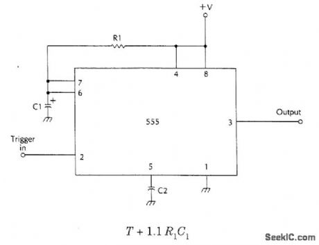
BASIC_555_MONOSTABLE
Published:2009/6/24 22:24:00 Author:May
View full Circuit Diagram | Comments | Reading(848)
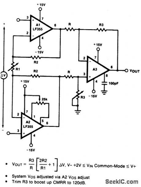
HIGH_IMPEDANCE_LOW_DRIFT_INSTRUMENTATION_AMPLIFIER
Published:2009/6/24 22:24:00 Author:May
View full Circuit Diagram | Comments | Reading(556)
SINE_COSINE_AUDIO_GENERATOR_FOR_GALVANOMETER_EXPERIMENTS_
Published:2009/6/24 22:24:00 Author:May
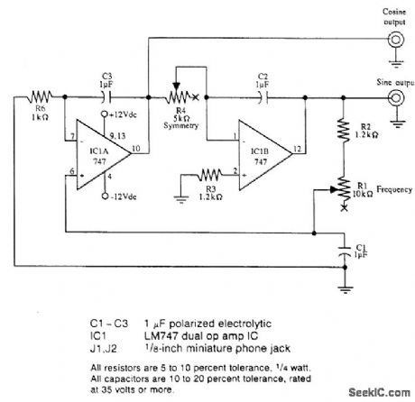
This circuit shows how to implement a sine/cosine audio generator for operating two galvanometers. (View)
View full Circuit Diagram | Comments | Reading(748)
| Pages:1323/2234 At 2013211322132313241325132613271328132913301331133213331334133513361337133813391340Under 20 |
Circuit Categories
power supply circuit
Amplifier Circuit
Basic Circuit
LED and Light Circuit
Sensor Circuit
Signal Processing
Electrical Equipment Circuit
Control Circuit
Remote Control Circuit
A/D-D/A Converter Circuit
Audio Circuit
Measuring and Test Circuit
Communication Circuit
Computer-Related Circuit
555 Circuit
Automotive Circuit
Repairing Circuit