
Circuit Diagram
Index 1324
SOLID_STATE_BATTERY_VOLTAGE_INDICATOR
Published:2009/6/24 22:24:00 Author:May

View full Circuit Diagram | Comments | Reading(685)
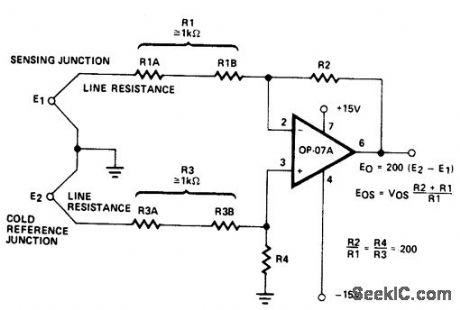
1HIGH_STABILITY_THERMOCOUPLE_AMPLIFIER
Published:2009/6/24 22:23:00 Author:May
View full Circuit Diagram | Comments | Reading(606)
CURRENT_LIMITED_6_V_CHARGER
Published:2009/6/24 22:22:00 Author:May

View full Circuit Diagram | Comments | Reading(1)
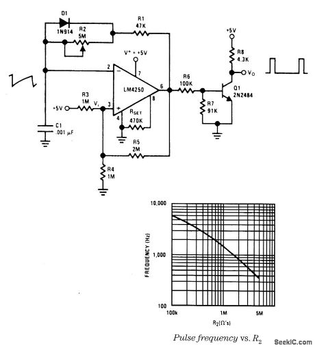
LOW_FREQUENCY_PULSE_GENERATOR
Published:2009/6/24 22:22:00 Author:May
View full Circuit Diagram | Comments | Reading(630)
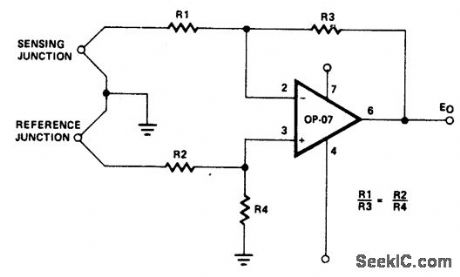
HIGH_STABILITY_THERMOCOUPLE_AMPLIFIER
Published:2009/6/24 22:22:00 Author:May
View full Circuit Diagram | Comments | Reading(1832)
FAST_CHARGER_FOR_NI_CAD_BATTERIES
Published:2009/6/24 22:22:00 Author:May

View full Circuit Diagram | Comments | Reading(648)
TRIANGLE_WAVE_GENERATOR_1
Published:2009/6/24 22:22:00 Author:May
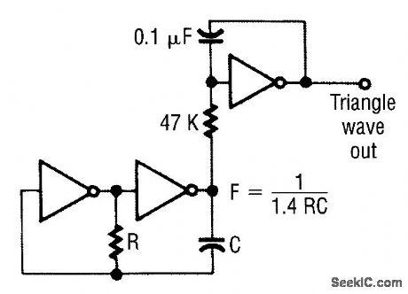
The first two gates are set up as a square-wave oscillator, and the last one makes the conversion to triangle waves. (View)
View full Circuit Diagram | Comments | Reading(790)
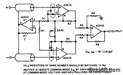
PRECISION_FET_INPUT_INSTRUMENTATION_AMPLIFIER
Published:2009/6/24 22:21:00 Author:May

View full Circuit Diagram | Comments | Reading(507)
LOW_COST_TRICKLE_CHARGER_FOR_12_V_STORAGE_BATTERY
Published:2009/6/24 22:21:00 Author:May

Circuit Charge rate can be varied and is based on the size of bulb. (View)
View full Circuit Diagram | Comments | Reading(444)
GENERATE_ACCURATE_PWM_SIGNALS
Published:2009/6/24 22:21:00 Author:May

Accurate 10 to 90% duty-cycle PWM signals can be generated using this simple circuit setup.The desired duty cycle is selected by a single jumper block. PWM clock IC1 runs at 10x the desired pulse drive frequency. IC2, a 4017 divide-by-10 counter, decodes the clock pulses into one of 10 out-puts. Output 0 resets IC3, the PWM latch. The latch stays reset until the desired duty-cycle output set by the jumper block is reached. At this point, the PWM Iatch is set, and the PWM output line re-mains high until output 0 is decoded again.By calling IC2's output (0) the reset line for the latch, the PWM output is forced inactive if the jumper strap is rernoved to change duty cycles without first powering down.Using the zero-state reset allows IC2's reset pin to be used as an on/off control line for the cir-cuit. The complementary PWM output could be used in a full bridge design. (View)
View full Circuit Diagram | Comments | Reading(1838)
BATTERY_CHARGING_REGULATOR
Published:2009/6/24 22:20:00 Author:May

The circuit is capable of charging a 12 volt battery at up to a six ampere rate. Other volt-ages andcurrents, from6 to600volts and upto 300 amperes, can be accommodated by suitable component selection. When the battery voltage reaches its fully charged level, the charging SCR shuts off, and a trickle charge as deter-mined by the value of R4 continues to flow. (View)
View full Circuit Diagram | Comments | Reading(1984)
TRIANGLE_WAVE_GENERATOR
Published:2009/6/24 22:20:00 Author:May

This oscillator, which is built around an LM1458 dual op amp and a few inexpensive components, produces a 2-V peak-to-peak, triangular waveform. (View)
View full Circuit Diagram | Comments | Reading(0)
SIMPLE_TRIANGLE_WAVEFORM_GENERATOR
Published:2009/6/24 22:19:00 Author:May
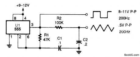
The circuit is a triangle waveform-generator circuit that uses as few parts as possible. A 555 timer IC, two resistors, and two capacitors make the triangle waveform. The IC is connected in a 50% duty-cycle astable square-wave oscillator circuit. The square-wave output is fed from pin 3 of the IC to an RC shaping circuit.When the 555's square-wave output goes high, C2 begins to charge through R2 and the voltage across C2 increases as long as the output remains high. When the IC's output goes low again, C2 be-gins to discharge through R2 reducing the voltage across C2 as long as the output remains low. The resulting waveform across C2 takes the shape of a triangle. The best waveform linearity is obtained when R2 and C2 are made as large as possible. With the component values shown, the peak-to-peak output is 0.5 V at a frequency of about 200 Hz. (View)
View full Circuit Diagram | Comments | Reading(2)
SIMPLE_NI_CAD_BATTERY_ZAPPER
Published:2009/6/24 22:19:00 Author:May

This circuit is used to clear internal shorts in nickel cadmium batteries. To operate, connect ni-cad to output and press the pushbutton for three seconds. (View)
View full Circuit Diagram | Comments | Reading(747)
VARIABLE_GAIN_AMPLIFIER
Published:2009/6/24 22:18:00 Author:May
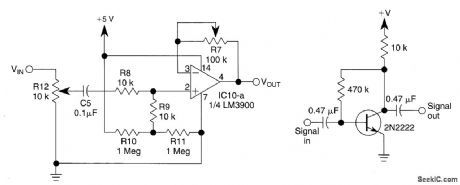
This circuit uses 1/4 of an LM3900 to build a simple variable-gain front end for an oscilloscope. R7 is the gain control. Also shown is a simple preamp if you need more than 10X of gain. (View)
View full Circuit Diagram | Comments | Reading(2028)
NI_CAD_CHARGER
Published:2009/6/24 22:18:00 Author:May

This circuit uses constant current LEDs to adjust charging current. It makes use of LEDs that pass a constant current of about 15 mA for an applied voltage range of 2-18 V. They can be paralleled to give any multiple of 15 mA and they light up when current is flowing. The circuit will charge a single cell at 15, 30 or 45 mA or cells in series up to the rated supply voltage limit (about 14 V). (View)
View full Circuit Diagram | Comments | Reading(603)
VERY_HIGH_IMPEDANCE_INSTRUMENTATION_AMPLIFIER__
Published:2009/6/24 22:17:00 Author:May
View full Circuit Diagram | Comments | Reading(511)
CONSTANT_VOLTAGE,CURRENT_LIMITED_CHARGER
Published:2009/6/24 22:17:00 Author:May

For 12 V sealed lead-acid batteries. (View)
View full Circuit Diagram | Comments | Reading(923)
TRIGGER_SELECTION_CIRCUIT_FOR_OSCILLOSCOPE_TIMEBASE
Published:2009/6/24 22:17:00 Author:May

View full Circuit Diagram | Comments | Reading(633)
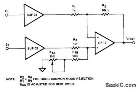
HIGH_SPEED_INSTRUMENTATION_AMPLIFIER_
Published:2009/6/24 22:16:00 Author:May
View full Circuit Diagram | Comments | Reading(465)
| Pages:1324/2234 At 2013211322132313241325132613271328132913301331133213331334133513361337133813391340Under 20 |
Circuit Categories
power supply circuit
Amplifier Circuit
Basic Circuit
LED and Light Circuit
Sensor Circuit
Signal Processing
Electrical Equipment Circuit
Control Circuit
Remote Control Circuit
A/D-D/A Converter Circuit
Audio Circuit
Measuring and Test Circuit
Communication Circuit
Computer-Related Circuit
555 Circuit
Automotive Circuit
Repairing Circuit