
Circuit Diagram
Index 1327
CAR_BATTERY_MONITOR
Published:2009/6/24 21:52:00 Author:May

Waring light (LED) indicates when battery Voltage falls below level set by 10 K pot. Can indicate that battery is defective or needs charging if cranking drops battery vlotage belpw preset safe limit. (View)
View full Circuit Diagram | Comments | Reading(839)
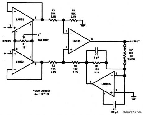
BRIDGE_TRANSDUCER_AMPLIFIER
Published:2009/6/24 21:52:00 Author:May
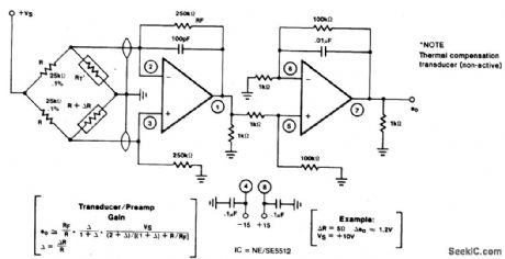
View full Circuit Diagram | Comments | Reading(1027)
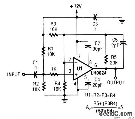
VIDEO_DRIVER_AMPLIFIER
Published:2009/6/24 21:52:00 Author:May
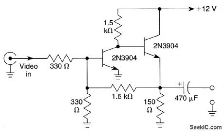
This simple circuit has a voltage gain of about 5x and will drive low-impedance loads (75 Ω) to 1.5 V p-p or better. (View)
View full Circuit Diagram | Comments | Reading(687)
4093_CMOS_VFO
Published:2009/6/24 21:52:00 Author:May

Two gates of a Quad 4093 are used in an astable multivibrator. C1 is a three-gang 365 pF variable capacitor with sections paralleled. S3 and S4 switch in optional extra capacitors. (View)
View full Circuit Diagram | Comments | Reading(2665)
250_mA_60_MHz_CURRENT_FEEDBACK_AMPLIFIER_FOR_VIDEO_APPLICATIONS
Published:2009/6/24 21:51:00 Author:May
View full Circuit Diagram | Comments | Reading(450)
BATTERY_POWERED_BUFFER_AMPLIFIER_FOR_STANDARD_CELL
Published:2009/6/24 21:51:00 Author:May

This circuit has negligible loading and disconnects the cell for low supply voltage or overload on output. The indicator diode extinguishes as disconnect circuitry is activated. (View)
View full Circuit Diagram | Comments | Reading(506)
TWISTED_PAIR_VIDEO_DRIVER_RECEIVER_CIRCUIT
Published:2009/6/24 21:51:00 Author:May

This circuit should be useful where a twisted-pair video line is to be used. R1 is adjusted for proper gain (monitor brightness and contrast) and C1 is adjusted for best color. (View)
View full Circuit Diagram | Comments | Reading(1177)
ICE_WARNING_AND_LIGHTS_REMINDER
Published:2009/6/24 21:50:00 Author:May

This device will tell a driver if his lights should be on and will warn him if the outside temperature is nearing zero by lighting a LED and sounding a buzzer9 VR1 adjusts sensitivity for temperature, VR2 for light. Both thermistor and LDR should be well protected. Most high gain NPN transistors will work. (View)
View full Circuit Diagram | Comments | Reading(630)
CHOPPER_CHANNEL_AMPLIFIER
Published:2009/6/24 21:50:00 Author:May
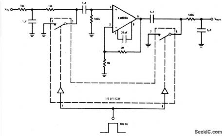
View full Circuit Diagram | Comments | Reading(441)
VIDEO_AMPLIFIER
Published:2009/6/24 21:50:00 Author:May
View full Circuit Diagram | Comments | Reading(0)
SIMPLE_AUDIO_TEST_OSCILLATOR
Published:2009/6/24 21:50:00 Author:May

An 88-mH surplus telephone toroidal coil is used in a 1-kHz oscillator. Up to 8 V p-p into a high-Z load is available. THD is 0.9%. (View)
View full Circuit Diagram | Comments | Reading(1116)
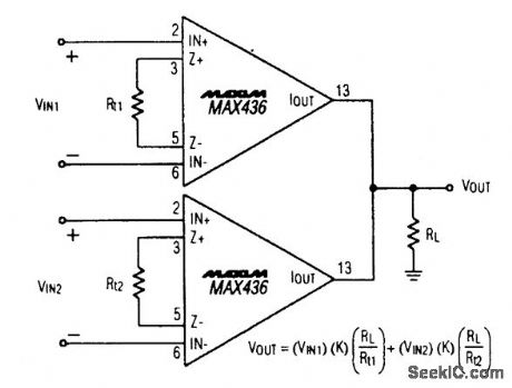
VIDEO_SUMMING_AMPLIFIER
Published:2009/6/24 21:50:00 Author:May
View full Circuit Diagram | Comments | Reading(471)
ADJUSTABLE_VIDEO_CABLE_EQUALIZER
Published:2009/6/24 21:49:00 Author:May

The figure is a complete schematic of the cable equalizer. The LT1256 (U1) is a two-input/one-output 40-MHz current feedback amplifier with a linear control circuit that sets the amount that each input contributes to the output. One amplifier (input pins 13 and 14) of the LT1256 is configured as a gain of one with no frequency equalization. The other amplifier (input pins 1 and 2) has frequency equalizing components in parallel with the 12-kΩ gain resistor. An additional amplifier (U2, LT1227) is used to set the overall gain. Two amplifiers were used here to make setting the gain a single ad-justment, but in a production circuit, the LT1256 can be configured to have the necessary gain and the whole function can be done with one chip. (View)
View full Circuit Diagram | Comments | Reading(803)
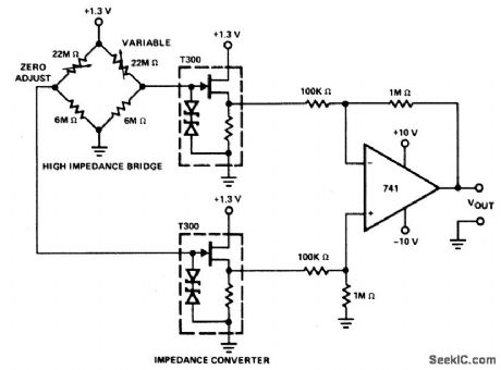
LOW_SIGNAL_LEVEL,HIGH_IMPEDANCE_INSTRUMENTATION_AMPLIFIER
Published:2009/6/24 21:49:00 Author:May
View full Circuit Diagram | Comments | Reading(710)
WINDSHIELD_WIPER_HESITATION_CONTROL_UNIT
Published:2009/6/24 21:49:00 Author:May


This circuit uses the 555 timer in the asta-ble or oscillatory mode. The length of time the timer is off is a function of the values of C1, R2, and R3. The potentiometer which controls the amount of hesitation . (Approximately 2 to 15 seconds.) R2 provides a minimum time delay when R3 is at its zero ohms position. (View)
View full Circuit Diagram | Comments | Reading(849)
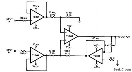
1INSTRUMENTATION_AMPLIFIER
Published:2009/6/24 21:48:00 Author:May
View full Circuit Diagram | Comments | Reading(0)
4093_CMOS_ASTABLE_OSCILLATOR
Published:2009/6/24 21:48:00 Author:May

Two gates of the Quad 4093 are used to make an oscillator. RX can be from about 5 kΩ to around 10 MΩ. CX can be from about 10 pF to many μF, the limit being set by the leakage of the capacitor. Frequency is approximately 2.8/RXCX (R MΩ, Cmfd). (View)
View full Circuit Diagram | Comments | Reading(3793)
VIDEO_SWITCH
Published:2009/6/24 21:48:00 Author:May

Using National Semiconductor LH4266 and LH4006, this circuit switches one of two inputs to four output (75Ω) lines. (View)
View full Circuit Diagram | Comments | Reading(1)
VARIABLE_GAIN,DIFFERENTIAL_INPUT_INSTRUMENTATION_AMPLIFIER
Published:2009/6/24 21:48:00 Author:May
View full Circuit Diagram | Comments | Reading(499)
SIMPLE_VIDEO_GRAY_SCALE_GENERATOR_EUROPEAN_LINE_STANDARD
Published:2009/6/24 21:47:00 Author:May

A simple gray-scale generator (staircase waveform) can be obtained with a CD4060 counter, a 1-MHz crystal oscillator, and several resistors to act as an elementary D/A converter to convert the binary count output to analog equivalent. This circuit is for European (PAL) standards. (View)
View full Circuit Diagram | Comments | Reading(2550)
| Pages:1327/2234 At 2013211322132313241325132613271328132913301331133213331334133513361337133813391340Under 20 |
Circuit Categories
power supply circuit
Amplifier Circuit
Basic Circuit
LED and Light Circuit
Sensor Circuit
Signal Processing
Electrical Equipment Circuit
Control Circuit
Remote Control Circuit
A/D-D/A Converter Circuit
Audio Circuit
Measuring and Test Circuit
Communication Circuit
Computer-Related Circuit
555 Circuit
Automotive Circuit
Repairing Circuit