
Circuit Diagram
Index 1331
CMOS_VFO
Published:2009/6/24 21:31:00 Author:Jessie

The circuit shown has a frequency range of 2 Hz to 30 kHz. R2 is a linear or log potentiometer. (View)
View full Circuit Diagram | Comments | Reading(1241)
IR_REMOTE_CONTROL_TRANSMITTER/RECEIVER
Published:2009/6/24 21:30:00 Author:Jessie
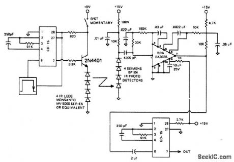
The circuit is designed to operate at 25 kHz. The data stream turns the 2N4401 hard on or off depending upon the coded state. This in turn switches the series infrared LEDs on and off. The receiver circuit consists of a three stage amplifier with photo diodes arrayed for maximum coverage of the reception area. The range of this set-up should be about 10 meters. (View)
View full Circuit Diagram | Comments | Reading(2411)
WIRELESS_MICROPHONE
Published:2009/6/24 21:20:00 Author:May

An op-amp IC (741) amplifies the audio signal from MIC1, and R12 controls its gain. Audio is fed to the oscillator circuit Q1 and related components. D2 is a varactor diode. Audio fed to D2 causes FM of the oscillator signal. L1 is 1/2 turns of #18 wire on a He diameter form. The antenna is a 12 whip. (View)
View full Circuit Diagram | Comments | Reading(0)
IR_TYPE_DATA_LINK
Published:2009/6/24 21:29:00 Author:Jessie

View full Circuit Diagram | Comments | Reading(1278)
MICRO_TV_TRANSMITTER
Published:2009/6/24 21:19:00 Author:May

For very low power noncritical applications, this small TV modulator can be useful as a shortrange (50 feet) transmitter for video signals. A small camera module can be used as a source. R11 is used to vary dc offset of the modulator. (View)
View full Circuit Diagram | Comments | Reading(0)
LOCAL_OSCILLATOR_FOR_DOUBLE_BALANCED_MIXERS
Published:2009/6/24 21:19:00 Author:May
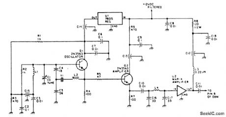
This circuit has an amplifier to supply +10 dBm to an SBL series (Mini-circuits) or similar type doubly-balanced mixer assembly. This circuit has values shown for =80- to 90-MHz crystals, although values of oscillator circuit constants can be scaled for higher or lower frequencies. (View)
View full Circuit Diagram | Comments | Reading(0)
CRYSTAL_OSCILLATOR
Published:2009/6/24 21:28:00 Author:Jessie

Circuit NotesStable VXO using 6-or 8-MHz crystals uses a capacitor and an inductor to achieve frequency pulling on either side of series resonance. (View)
View full Circuit Diagram | Comments | Reading(215)
WIRELESS_GUITAR_TRANSMITTER
Published:2009/6/24 21:16:00 Author:May

This transmitter has a built-in distortion effects unit and a touch switch to switch effects off and on. The circuit operates from a 9-V battery. IC1-a and IC1-b are used in the effects circuitry. IC1-d is an input preamp and IC2 is a quad analog switch to handle audio switching. Q1 acts as a varactor diode modulator while IC-4 is an 88- to 108-MHz FM oscillator. (View)
View full Circuit Diagram | Comments | Reading(0)
VARIABLE_WIEN_BRIDGE_OSCILLATOR
Published:2009/6/24 21:15:00 Author:May

This circuit uses a single potentiometer to tune a 300- to 3000-Hz range. A FET op amp is used at A1 and A2. The upper frequency limit is determined by the gain-bandwidth product of the op amps. (View)
View full Circuit Diagram | Comments | Reading(0)
IONIZATION_CHAMBER_SMOKE_DETECTOR
Published:2009/6/24 21:15:00 Author:May

Battery-operated, ionization chamber smoke detector includes a circuit to generate a unique alarm when the battery reaches the end of its useful life. The circuit uses the MCMOS MC14572 for two alarm oscillators (smoke and low battery). This circuit additionally uses five discrete transistors as buffers and comparators. (View)
View full Circuit Diagram | Comments | Reading(0)
ULTRASONIC_REMOTE_CONTROL_TESTER
Published:2009/6/24 21:27:00 Author:Jessie
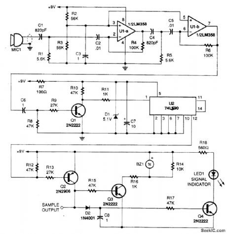
This circuit picks up the ultrasonic tone via MIC1, amplifies it, and divides it by 10 in IC U2, a 74LS90. The output of U2 drives an audio amplifier and a piezoelectric element is used as a speaker. (View)
View full Circuit Diagram | Comments | Reading(1818)
SIGNAL_TRACER
Published:2009/6/24 21:13:00 Author:May

This circuit uses a simple detector-audio am-plifier. The output can be connected to head-phones or another audio amplifier. (View)
View full Circuit Diagram | Comments | Reading(0)
VISUAL_ZERO_BEAT_INDICATOR
Published:2009/6/24 21:27:00 Author:Jessie

Light-emitting diodes connected with re-verse polarity provide a visual indication of zero-beat ffequency. Each LED is on for only half a cycle of the input. When the input fre-quency is more than 1 kilohertz away from the zero-beat frequency, both LEDs appear to be on all the time. As the input frequency comes within about 20 hertz of zero beat, the LEDs will flicker until zero beat is reached. Both LEDs glow or flicker until zero beat is reached, when they go out. (View)
View full Circuit Diagram | Comments | Reading(0)
GAS_AND_SMOKE_DETECTOR
Published:2009/6/24 21:13:00 Author:May
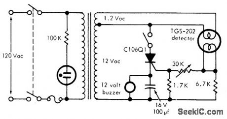
This circuit can detect smoke and a number of gases (CO, CO2, methane, coal gas and others) with a 10 ppm sensitivity. It uses a heated surface semiconductor sensor. Detection occurs when the gas concentration in-crease causes a decrease of the sensor element internal resistance. The switch in series with the SCR is used for resetting the alarm. (View)
View full Circuit Diagram | Comments | Reading(0)
ZERO_CENTER_INDICATOR_FOR_FM_RECEIVERS
Published:2009/6/24 21:26:00 Author:Jessie

To adjust, tune in a station and adjust the 1 M pot for a null. Then ask the station to modulate and fine adjust so modulation peaks don't light the LEDs. Stations are properly tuned when neither LED is lit. (View)
View full Circuit Diagram | Comments | Reading(1160)
CABLE_TRACER
Published:2009/6/24 21:12:00 Author:May

This circuit generates a 1-kHz square wave for cable tracing. Because this circuit is simple and generates from 1.5 V, several can be used at the same time to generate multiple tones for tracing multiconductor cables. (View)
View full Circuit Diagram | Comments | Reading(0)
LOW_COST_6_W,40_M_CW_TRANSMITTER
Published:2009/6/24 21:26:00 Author:Jessie
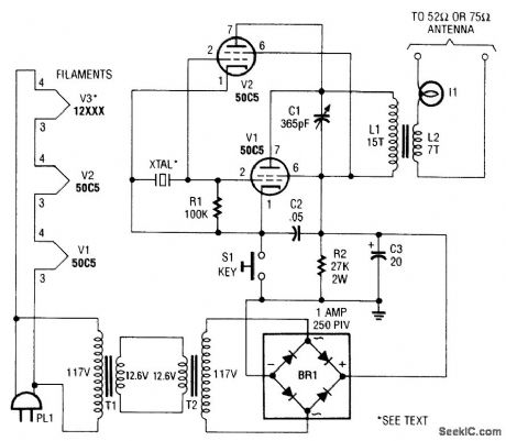
L1 and L2 are wound on a 7/8 diameter form. L1 is 15 turns #22 plastic-covered wire, and L2 is 7 turns #22 plastic-covered wire. (View)
View full Circuit Diagram | Comments | Reading(1603)
BASIC_OSCILLATOR_CIRCUITS
Published:2009/6/24 21:12:00 Author:May


Five basic types of LC oscillators are shown. The frequency can be changed by using the formula:where Leffective =equivalent inductance Ceffective =equivalent capacitance (View)
View full Circuit Diagram | Comments | Reading(0)
WIRE_TRACER
Published:2009/6/24 21:12:00 Author:May

This tracer works by placing a square-wave signal on the line to be traced. The square wave is rich in harmonics. A small transistor radio placed close to a wire carrying this signal will buzz. The ra-dio, therefore, is used as a probe to trace out the wire. (View)
View full Circuit Diagram | Comments | Reading(0)
PROXIMITY_ALARM
Published:2009/6/24 21:10:00 Author:May

View full Circuit Diagram | Comments | Reading(0)
| Pages:1331/2234 At 2013211322132313241325132613271328132913301331133213331334133513361337133813391340Under 20 |
Circuit Categories
power supply circuit
Amplifier Circuit
Basic Circuit
LED and Light Circuit
Sensor Circuit
Signal Processing
Electrical Equipment Circuit
Control Circuit
Remote Control Circuit
A/D-D/A Converter Circuit
Audio Circuit
Measuring and Test Circuit
Communication Circuit
Computer-Related Circuit
555 Circuit
Automotive Circuit
Repairing Circuit