Circuit Diagram
Index 1328
WINDSHIELD_WIPER_CONTROLLER
Published:2009/6/24 21:47:00 Author:May

This circuit provides complete speed con-trol over car's windshield wipers. They can be slowed down to any rate even down to four sweeps per minute. The controller has two principal circuits: The rate-determining circuit-a unijunction transistor connected as a freerunning oscillator, and the silicon-controlled rectifier which is the actuator. (View)
View full Circuit Diagram | Comments | Reading(898)
LEVEL_SHIFTING_ISOLATION_AMPLIFIER
Published:2009/6/24 21:47:00 Author:May
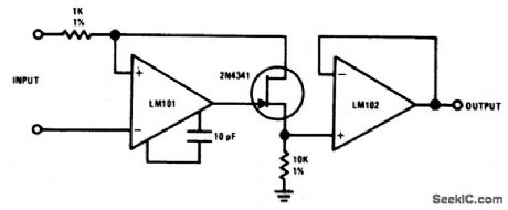
The 2N4341 JFET is used as a level shifter between two op amps operated at different power supply voltages. The JFET is ideally suited for this type of application because ID=IS. (View)
View full Circuit Diagram | Comments | Reading(901)
LM12O1_VIDEO_AMPLIFIER
Published:2009/6/24 21:46:00 Author:May
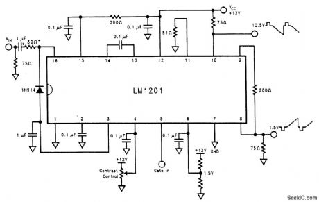
This video amplifier has 75-Ω bi-phase outputs. (View)
View full Circuit Diagram | Comments | Reading(562)
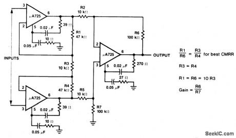
INSTRUMENTATION_AMPLIFIER_WITH_HIGH_COMMON_MODE_REJECTION
Published:2009/6/24 21:46:00 Author:May
View full Circuit Diagram | Comments | Reading(640)
SIMPLE_NTSC_GRAY_SCALE_VIDEO_GENERATOR
Published:2009/6/24 21:46:00 Author:May

A 4.032-MHz crystal oscillator (256 x horizontal line scan rate) drives a BCD counter. The binary outputs of the counter are fed to R2 through R5, a simple weighting network for D/A conversion, re-sulting in a staircase video output with a rep rate of 15.75 kHz. This circuit should be useful for am-ateur TV linearity testing and setup purposes. (View)
View full Circuit Diagram | Comments | Reading(2434)
ADJUSTABLE_VFO_TEMPERATURE_COMPENSATOR
Published:2009/6/24 21:45:00 Author:May

Use of a differential capacitor allows temperature compensation of LC circuit using an NPO and N1500 ceramic. C6 is a differential capacitor that has two stators and one common rotor. When one capacitance (stator) is maximum, the other is minimum. L1, C1, C2, and C3 are tuning, trimming, and fixed capacitors, respectively. (View)
View full Circuit Diagram | Comments | Reading(0)
VIDEO_CABLE_DRIVER
Published:2009/6/24 21:45:00 Author:May

This is a MAX436 coaxial-cable driving circuit (View)
View full Circuit Diagram | Comments | Reading(0)
VIDEO_IF_AMPLIFIER_DETECTOR
Published:2009/6/24 21:44:00 Author:May
View full Circuit Diagram | Comments | Reading(0)
NTSC_TO_RGB_CONVERTER
Published:2009/6/24 21:43:00 Author:May

This circuit takes baseband NTSC video, decodes it, and derives RGB video suitable for driving a color multisync computer monitor. This enables the user to take advantage of the generally better resolution of computer monitors. (View)
View full Circuit Diagram | Comments | Reading(0)
VARIABLE_DUTY_CYCLE_OSCILLATOR
Published:2009/6/24 21:42:00 Author:May

Using a potentiometer and steering diodes, this 1.2-kHz oscillator will provide 1 to 99% duty cycle. Vary C1 to change frequency. (View)
View full Circuit Diagram | Comments | Reading(0)
ONE_OF_TWO_VIDEO_SELECTOR
Published:2009/6/24 21:41:00 Author:May
View full Circuit Diagram | Comments | Reading(577)
RGB_VIDEO_AMPLIFIER
Published:2009/6/24 21:41:00 Author:May
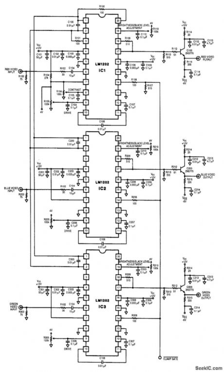
This circuit is a three-channeL RGB video amplifer with individual brightness,black level and drive controls. (View)
View full Circuit Diagram | Comments | Reading(926)
PROXIMITY_DETECTOR
Published:2009/6/24 21:41:00 Author:May

This circuit provides a means of detecting the presence of anything by the reflection of infra-red light and provides a direct digital output of object detection. By the use of modulation and high power bursts of infra-red at a very low duty cycle, a detection range of over a foot is achieved. Works on the principle of transmitting a beam of modulated infra-red light from the emitter diode LED2, and receiving reflections from objects passing in front of the beam with a photodiode detector D1. The circuit consists o f an infra-red transmitter, photodiode amplifier, and a variable threshold comparator. (View)
View full Circuit Diagram | Comments | Reading(2552)
ANALOG_DEVICES
Published:2009/6/24 21:39:00 Author:May

The AD8001 has been designed to offer outstanding performance as a video line driver. The im-portant specification of differential gain (0.01%) and differential phase (0.025°) meet the most ex-acting HDTV demands for driving one video load. The AD8001 also drives up to two back-terminated loads with equally impressive performance (0.01%, 0.07°). Another important consideration is isola-tion between loads in a multiple-load application. The AD8001 has more than 40 dB of isolation at 5 MHz when driving two 75-Ω terminated loads. (View)
View full Circuit Diagram | Comments | Reading(912)
WIEN_BRIDGE_AUDIO_OSCILLATOR
Published:2009/6/24 21:39:00 Author:May
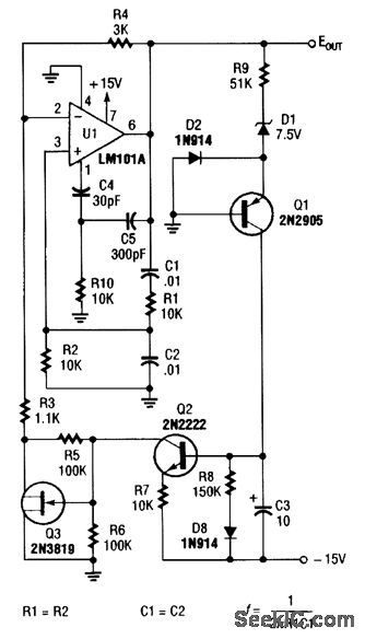
For variable-frequency operation, R1 and R2 can be replaced by a dual potentiometer. (View)
View full Circuit Diagram | Comments | Reading(687)
VIDEO_TITLER
Published:2009/6/24 21:38:00 Author:May


The figure shows the schematic of the video titler circuit. The power-on reset function is generated by IC7, a Maxim MAX699 reset, and watchdog pulse generator. That device supplies a reset pulse of 140 to 500 ms at power-up. This is accomplished with some external parts, as well as the OSD controller in IC1. First, the horizontal and vertical sync from the composite video input is detected by IC2, which is set for NTSC specification horizontal and vertical synchronization timing via resistor R4.The detected horizontal and vertical sync is fed to IC1. The OSC controller in IC1 uses these sig-nals to internally synchronize the overlay text to the incoming video. The frequency of the dot clock is controlled by components L1, C5, and C6. Text is overlaid by video multiplexer IC5, which is con-trolled by IC1.The overlay character outline and intensity are controlled via solid-state potentiometers, allow-ing the microcontroller to control the position of their wipers and store the settings in an onboard EEPROM. The microcontroller's OSC logic controls the multiplexer timing from the BF (IC1, pin 30) and VIDCTL (IC1, pin 25) signals. The BF signal switches the video multiplexer between character and character-outline video, and VIDCTL switches the multiplexer between the input video and the overlay video from IC1. The dc levels from IC3 and IC4 set the character and outline intensity, and these levels are fed to video multiplexer IC5.The video titler can store and recall text from EEPROM IC6, which has enough capacity to store one overlay screen and other required data, such as network address, horizontal and vertical overlay fine position, and type of interface.The RS-232 interface is provided by a MAX202 transceiver. The RS-485 interface is provided by an LTC485 transceiver that provides both transmit and receive functions. The keyboard interface is basically a direct connection to the microprocessor. (View)
View full Circuit Diagram | Comments | Reading(799)
PRECISION_GATED_OSCILLATOR
Published:2009/6/24 21:37:00 Author:May
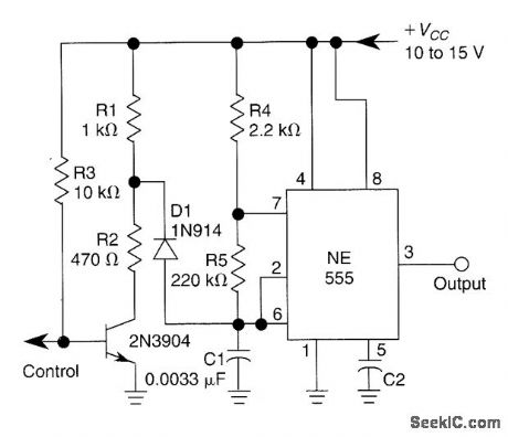
A 1-kHz gated oscillator with no long turn-on cycle is shown. R2, R3, and D1 preset the voltage on tuning capacitor C1 to 1/3 of the supply voltage. (View)
View full Circuit Diagram | Comments | Reading(818)
REMOTE_LOUDSPEAKER_VIA_IR_LINK
Published:2009/6/24 21:36:00 Author:May
View full Circuit Diagram | Comments | Reading(642)
IR_TRANSMITTER
Published:2009/6/24 21:36:00 Author:May
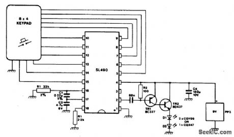


This simple infra-red transmitter, where the PPM output from pin 2 of the SL490 is fed to the base of the PNP trasmitter TR1, produces an amplified current pulse about 15,μsec wide. This pulse is further amplified by TR2 and applied to the infra-red diodes D1 and D2. (View)
View full Circuit Diagram | Comments | Reading(1714)
ULTRASONIC_SOUND_RECEIVER
Published:2009/6/24 21:35:00 Author:May
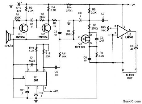
You won't be disappointed with the performance of this sensitive ultrasonic receiver. It can let you listen to bugs, bats, engines, and virtually any other source of ultrasonic sounds. This circuit uses a piezo tweeter as an ultrasonic microphone, amplifier stages Q1, Q2, and an LO using a 567IC. Q3 is a mixer that heterodynes the ultrasonic sounds down to the audible range. U2 is an amplifier that will drive a pair of headphones. (View)
View full Circuit Diagram | Comments | Reading(4435)
| Pages:1328/2234 At 2013211322132313241325132613271328132913301331133213331334133513361337133813391340Under 20 |
Circuit Categories
power supply circuit
Amplifier Circuit
Basic Circuit
LED and Light Circuit
Sensor Circuit
Signal Processing
Electrical Equipment Circuit
Control Circuit
Remote Control Circuit
A/D-D/A Converter Circuit
Audio Circuit
Measuring and Test Circuit
Communication Circuit
Computer-Related Circuit
555 Circuit
Automotive Circuit
Repairing Circuit
