
Circuit Diagram
Index 1330
INSTRUMENTATION_AMPLIFIER
Published:2009/6/24 21:42:00 Author:Jessie

Instrumentation amplifiers (differential amplifiers) are specifically designed to extract and amplify small differential signals from much larger common mode voltages. To serve as building blocks in instrumentation amplifiers, op amps must have very low offset voltage drift, high gain and wide bandwidth.The HA-4620/5604 is suited for this application. The optional circuitry makes use of the fourth amplifier section as a shield driver which enhances the ac common mode rejection by nullifying the effects of capac itance -to-ground mismatch between input conductors. (View)
View full Circuit Diagram | Comments | Reading(1195)
VARIABLE_DUTY_CYCLE_OSCILLATOR
Published:2009/6/24 21:42:00 Author:Jessie

Using a potentiometer and steering diodes, this 1.2-kHz oscillator will provide 1 to 99% duty cycle. Vary C1 to change frequency. (View)
View full Circuit Diagram | Comments | Reading(1152)
LOW_COST_6_W,40_M_CW_TRANSMITTER
Published:2009/6/24 21:26:00 Author:May
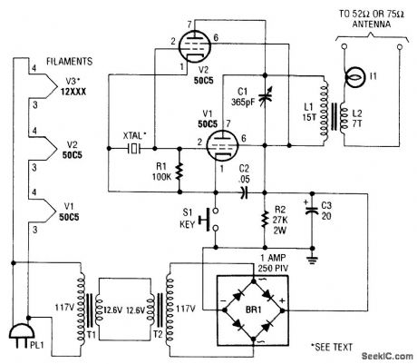
L1 and L2 are wound on a 7/8 diameter form. L1 is 15 turns #22 plastic-covered wire, and L2 is 7 turns #22 plastic-covered wire. (View)
View full Circuit Diagram | Comments | Reading(0)
WOLTAGE_LEVEL_DETECTOR
Published:2009/6/24 21:26:00 Author:May
View full Circuit Diagram | Comments | Reading(594)
SIMPLE_TTL_CRYSTAL_OSCILLATOR
Published:2009/6/24 21:25:00 Author:May

Circuit NotesThis simple and cheap crystal oscillator comprises one third of a 7404, four resistors and a crystal. The inverters are biased into their linear regions by RI to R4, and the crystal provides the feedback. Oscillation can only occur at the crystals fundamental frequency. (View)
View full Circuit Diagram | Comments | Reading(10041)
VISIBLE_VOLTAGE_INDICATOR_
Published:2009/6/24 21:25:00 Author:May

View full Circuit Diagram | Comments | Reading(571)
PRECISION_AUDIO_FREQUENCY_GENERATOR
Published:2009/6/24 21:25:00 Author:May

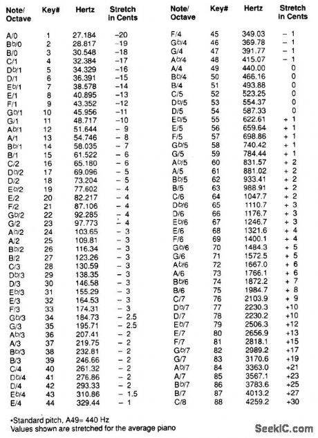
The precision audio-frequency generator consists of several subcircuits-an audio-amplifier/filter circuit, an automatic level control, a variable voltage-controlled oscillator, a frequency divider circuit, an integrator, and an audio output amplifier.
An electret microphone element is used to pick up the audio tone produced by the instrument. That signal is then fed to an amplifier/filter/level-controlled circuit and output via channel 1 (CH1) to an oscilloscope for display.
The variable voltage-controlled oscillator (VCO) is used to produce a signal offrom less than 10 kHz to more than 99 kHz. The VCO output is fed to a digital frequency counter for display, and is also routed to a chain of frequency dividers, where the signal is divided by 10, 100, or 1,000, depending on the setting of a selector switch.
From there, the selected signal frequency divides along two paths; one going to CH2 (which feeds the oscilloscope's sweep synchronization input) and to an integrator that converts the square-wave output of the divider into a triangular waveform. The output of the integrator is then amplified and fed to a set of stereo headphones via an audio output jack.
One section of the precision audio-frequency generator uses an electret microphone element to pick up audio from the piano. That signal is then processed and sent to one channel of a dual-trace oscilloscope. The other section of the circuit is used to produce a variable-frequency signal that is fed to a digital frequency counter and, after conditioning, is presented to the second channel of the scope and output to a set of stereo headphones. (View)
View full Circuit Diagram | Comments | Reading(2073)
LOW_POWER_VHF_BEACON_TRANSMITTER
Published:2009/6/24 21:25:00 Author:May
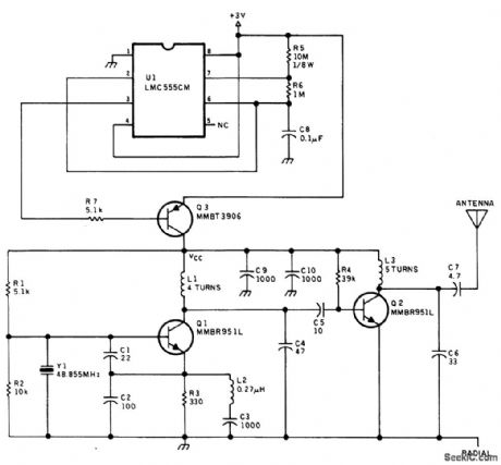
A crystal oscillator and tripler make up the low power beacon transmitter. U1 generates a pulse that keys the transmitter at a 10:1 duty cycle (100 ms on, 1 s off) to conserve battery power. This transmitter was used as a locator beacon. (View)
View full Circuit Diagram | Comments | Reading(1807)
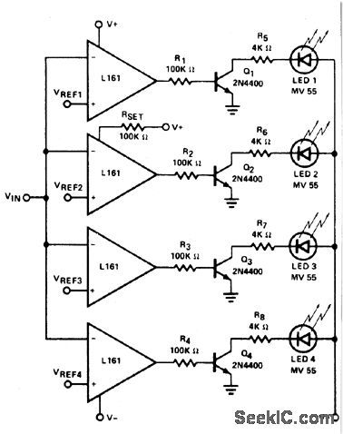
FIVE_STEP_VOLTAGE_LEVEL_INDICATOR
Published:2009/6/24 21:25:00 Author:May

This circuit provides a visual indication of the input analog voltage level. It has a high input impedance at pin 8 and open-collector outputs capable of sinking up to 40 milliam-peres. It is suitable for driving a linear array of 5 LEDs to indicate the level is 5 steps. The voltage at the analog input should be in the range of zero to approximately one volt and should never exceed eight volts. (View)
View full Circuit Diagram | Comments | Reading(703)
INDICATOR_AND_ALARM
Published:2009/6/24 21:24:00 Author:May

View full Circuit Diagram | Comments | Reading(847)
ULTRASONIC_cw_TRANSCEIVER
Published:2009/6/24 21:33:00 Author:Jessie

With the telegraph key at S2 up (open), the 567 PLL's input at pin 3 is coupled to the output of Q3. Transistors Q3 and Q4 are operat-ing in a high-gain, two-stage audio-amplifier circuit. The piezo speaker is coupled to the in-put of the amplifier though a 0.1-μF capacitor and a 680-Ω isolation resistor.In the receive mode, the piezo speaker oper-ates as a sensitive microphone. Ultrasonic signals travel from the microphone through the two-stage amplifier to the input of the 567, and, if the signal's frequency is within the IC's bandwidth, the LED will light and piezo-sounder BZ1 will sing out foreach dit and dah received. The receiver can be tuned to the incoming ultrasonic signal by adjust-ing R17. Of course, adjusting that potentiometer also changes the transmitter's frequency.The transmitter operates each time the S2 is closed. When the key is closed, diode D3 supplies a path to ground for BZ1, causing that sounder to produce an audible signal for each dit and dah transmitted. Also, Q2's bias is taken to ground through D2, allowing Q1 to pass the 567's square-wave signal on to the input of the power amplifier and out through the speaker. (View)
View full Circuit Diagram | Comments | Reading(2125)
FM_BUG
Published:2009/6/24 21:24:00 Author:May

View full Circuit Diagram | Comments | Reading(601)
FREQUENCY_SWITCHER
Published:2009/6/24 21:32:00 Author:Jessie

This transistor can achieve frequency switching in this CMOS astable oscillator. (View)
View full Circuit Diagram | Comments | Reading(1390)
THREE_STEP_LEVEL_INDICATOR
Published:2009/6/24 21:23:00 Author:May

This circuit makes a very compact level indicator where a meter would be impractical or not justified due to cost. Resistor values will depend on type of LED used. For MV50 LEDs the resistors are 2 K for steps of approx 2 V and current drain with all three LEDs on of 5 mA.The chain can be extended but current drain increases rapidly and the first LED carries all the current drawn from the supply. (View)
View full Circuit Diagram | Comments | Reading(661)
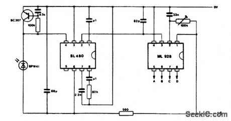
COMPACT_IR_RECEIVER
Published:2009/6/24 21:32:00 Author:Jessie
View full Circuit Diagram | Comments | Reading(1351)
BEAT_FREQUENCY_INDICATOR
Published:2009/6/24 21:22:00 Author:May

This circuit uses LEDs to display the beat frequency of two-tone oscillators. Only one LED is on at a time, and the apparent rotation of the dot is an exact indication of the best frequency. When f1 is greater than f2, a dot of light rotates clockwise; when f1 is less than f2, the dot rotates counterclockwise; and when f1 equals f2, there is no rotation. (View)
View full Circuit Diagram | Comments | Reading(787)
ULTRASONIC_MOTION_DETECTOR
Published:2009/6/24 21:32:00 Author:Jessie

A 567 PLL IC operates in a dual-function mode as a signal generator and an FM receiver. The 567's square-wave output at pin 5 is coupled to the base of Q1, and from Q1's emitter to the input of the power amplifier (Q2 and Q6). The output drives the piezo speaker, SPKR1.
The receive portion of the circuit operates as follows: transistors Q3 and Q4 are connected in a two-stage, high-gain, audio-frequency amplifier circuit, with the input connected to a second piezo speaker (SPKR2) operating as a sensitive microphone. The amplifier's output is coupled to the 567's input at pin 3. When an in-band signal is received, the LED lights.
The 567's FM output is coupled from pin 2 to the input of a very-low-frequency single-transistor amplifier, Q5. The amplifier's output at Q5's collector drives a voltage-doubler circuit (C11, D1, D2, and C12). The dc output feeds a 0- to 1-mA analog meter.
By placing the two pigzo speakers one foot apart and aiming them in the same direction, toward a nonmoving solid object, the signal from the transmitter's speaker urill reflect back into the receiver's speaker, and the frequency at the 567's input will be the same as the one being transmitted.
The ac output at pin 2 is zero when the outgoing and incoming frequencies are the same. How-ever, when the signal is reflected from a moving object, the received frequency will be either lower or higher than the transmitted one. If the object is moving away from the speakers, the received fre-quency will be lower; if the object is moving toward the speakers, the frequency will be higher.
The pin-2 signal is fed through a 470-pF capacitor to the base of Q5, where the signal is ampli-fied and fed to a voltage doubler, and then on to a meter circuit.
If you wish, the voltage doubter and meter can be removed and replaced with headphones connected between the negative side of C11 and circuit ground. That will allow you to listen to the difference-frequency signal as objects move in front of the speakers. (View)
View full Circuit Diagram | Comments | Reading(4519)
FM_STEREO_TRANSMITTER
Published:2009/6/24 21:21:00 Author:May

An FM stereo transmitter can be built around the BA1404 IC. This IC has all the functions necessary to generate an FM MPX signal. A separator oscillator circuit uses a 2N5210 transistor instead of the difficult-to-find 38-kHz crystal that is normally used. T1 is a 455-kHz IF transformer with 0.0039-μF capacitance added across it to enable tuning to 38 kHz. With this circuit, oscillator stabil-ity should be adequate. (View)
View full Circuit Diagram | Comments | Reading(0)
TEN_STEP_VOLTAGE_LEVEL_INDICATOR
Published:2009/6/24 21:21:00 Author:May

This ten-step adjustable analog level detector is capable of sinking up to 40 milliamperes at each output. The voltage range at the input pin should range from 0 to 2 volts. Circuits of this type are useful as liquid-level indicators, pressure indicators, and temperature tector dicators. They may also be used with a set of peres at active filters to provide a visual indication of input pin harmonic content of audio signals. (View)
View full Circuit Diagram | Comments | Reading(2370)
1IONIZATION_CHAMBER_SMOKE_DETECTOR
Published:2009/6/24 21:20:00 Author:May
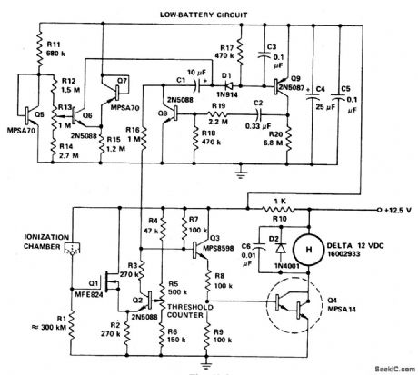
If the smoke alarm signal must be a continuous one rather than pulsating, then the slightly less expensive, all discrete transistor version of the MC14572 may be used. (View)
View full Circuit Diagram | Comments | Reading(0)
| Pages:1330/2234 At 2013211322132313241325132613271328132913301331133213331334133513361337133813391340Under 20 |
Circuit Categories
power supply circuit
Amplifier Circuit
Basic Circuit
LED and Light Circuit
Sensor Circuit
Signal Processing
Electrical Equipment Circuit
Control Circuit
Remote Control Circuit
A/D-D/A Converter Circuit
Audio Circuit
Measuring and Test Circuit
Communication Circuit
Computer-Related Circuit
555 Circuit
Automotive Circuit
Repairing Circuit