
Circuit Diagram
Index 1336
LOW_COST_STEP_DOWN_REGULATOR
Published:2009/6/24 5:10:00 Author:May

This inexpensive and efficient discrete step-down regulator is based on a complementary transistor arrangement that uses both positive and negative feedback and is referenced to a Zener diode. Inductor L1 is selected to maintain the switching frequency above the audible range for the intended operating load. The output filter L2 and C4 reduces ripple to less than 10 mV p-p over a large range of loads, with only a slight decrease in efficiency. (View)
View full Circuit Diagram | Comments | Reading(808)
LOGIC_CONTROL_OF_78XX_REGULATOR
Published:2009/6/24 5:09:00 Author:May

Transistors can be used to contorl any 78xx series regulator with logic signals.Both transistors are controlled by the logic level present at the base of Q1. (View)
View full Circuit Diagram | Comments | Reading(660)
33_V_1_A_SURFACE_MOUNT_REGULATOR
Published:2009/6/24 5:02:00 Author:May

This figure shown a tuopical LTC1265 surface-mount application.It provides 3.3 V at 1 A from an input voltage range of 4 V to 12 V.The peak efficiency approaches 93% at mid-current levels. (View)
View full Circuit Diagram | Comments | Reading(598)
NEGATIVE_VOLTAGE_REFERENCE
Published:2009/6/24 5:01:00 Author:May

D1 is used as a reference. R2, R3, and R4 are voltage dividers to obtain desired output voltage to the op-amp voltage follower. (View)
View full Circuit Diagram | Comments | Reading(704)
POSITIVE_VOLTAGE_REFERENCE
Published:2009/6/24 5:00:00 Author:May

D1 is used as a reference. R2, R3, and R4 provide desired output voltage to the op-amp voltage follower. (View)
View full Circuit Diagram | Comments | Reading(666)
LOW_VOLTAGE_REFERENCE
Published:2009/6/24 4:59:00 Author:May

This circuit illustrates a number of techniques that are useful for low-voltage, series-mode, power-efficient references. Intended for output currents of up to 10 mA, this design has an enabled standby current of about 100 μA; it can be easily programmed over a wide range of output voltages. (View)
View full Circuit Diagram | Comments | Reading(645)
1WWV_RECEIVER
Published:2009/6/24 4:58:00 Author:May
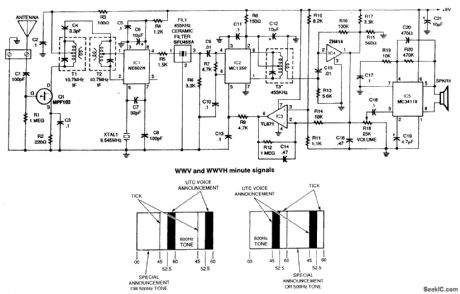
This receiver for 10-MHz WWV signals uses a 10.7-MHz FM receiver IF transformers as front-end components. It is a super-het with a 455-kHz IF frequency. By changing the front-end components 5- or 15-MHz reception could be obtained. A 3- to 6-foot antenna is usually adequate. (View)
View full Circuit Diagram | Comments | Reading(5634)
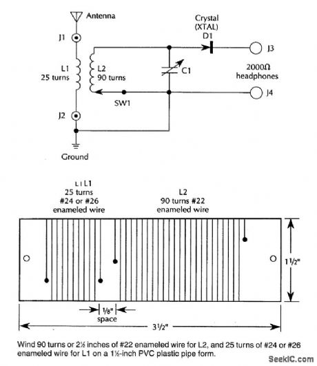
OLD_FASHIONED_CRYSTAL_RADIO
Published:2009/6/24 4:55:00 Author:May

L1 and L2 are wound on 4 diameter 10 form and are 200 tums of #24 wire. PVC pipe can be used. (View)
View full Circuit Diagram | Comments | Reading(604)
VARIOMETER_TUNED_RADIO
Published:2009/6/24 4:54:00 Author:May


The two fixed coils of the variometer, L1 and L3, are wound on an S)G-inch-long piece of 1-inch-diameter plastic pipe (its outer diameter is about 1 1/4 inches). Each coil is 2 1/4 inches long. The num-ber of turns is not critical, but 86 tightly wound turns of #22 enameled wire were used. When winding the coils, make sure you start at a point that will allow them to be placed 2 inches apart on the pipe. Drill holes in the pipe and run the leads of the coils out the end of the pipe that is closest to each.The movable coil, L2, is wound on a piece of 1 1/2-inch plastic pipe (its outer diameter is about 1 7/8inches). The winding is 2 inches long. Like L1 and L3, the actual number ofwindings of this coil are not critical, as long as the winding is approximately the right length. (View)
View full Circuit Diagram | Comments | Reading(732)
ECONOMY_SHORTWAVE_RECEIVER
Published:2009/6/24 4:51:00 Author:May
Using three transistors, this receiver covers the range of 6 to 17 MHz. Coils can be altered to change the range to a lower or higher frequency. (View)
View full Circuit Diagram | Comments | Reading(7769)
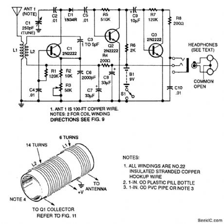
REGENERATIVE_RECEIVER_FOR_6_TO_17_MHz
Published:2009/6/24 4:49:00 Author:May

The headphones are 32-Ω stereo types.The common lead is left floating so that the two sides are in series,giving 64Ω. (View)
View full Circuit Diagram | Comments | Reading(0)
TOROIDAL_CORE_TRF_SHORTWAVE_RECEIVER
Published:2009/6/24 4:45:00 Author:May
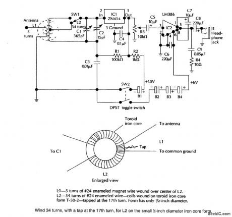
A ZN414 IC feeds an LM386 audio amplifier in this TRF circuit SW1is a band-switch,Coverageis up to 18 MHz. (View)
View full Circuit Diagram | Comments | Reading(0)
TREBLE_CONTROL_CIRCUIT
Published:2009/6/24 4:40:00 Author:May

This tone control has an insertion loss of 20 dB at flat setting and is effective above 1 kHz,It little effect below about 1 kHz. (View)
View full Circuit Diagram | Comments | Reading(0)
RECEIVER_PREAMP
Published:2009/6/24 4:37:00 Author:May
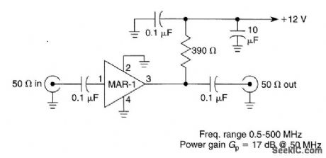
Suitable for HF and VHF receivers, this preamplifier can be mounted on the back of the receiver for a boost in gain. Useful gain is about 17 dB at 50 MHz (View)
View full Circuit Diagram | Comments | Reading(2784)
SUPERHET_FRONT_END
Published:2009/6/24 4:36:00 Author:May

This superhet receiver front end is simple and uses an NE602 followed by an MC1350 IF amplifier. (View)
View full Circuit Diagram | Comments | Reading(0)
LAMP_TIMER
Published:2009/6/24 4:35:00 Author:May
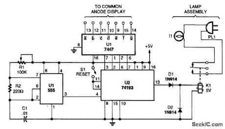

A timed switch uses a 555 oscillator/timer wired to operate in the astable mode. The timer sup-plies a positive pulse to the clock input of a 74193 4-bit binary up/down count every five minutes. Be-cause the 74193 is set to operate in the count-down mode, the output of the 555 is connected to the count-down input of the 74193.As the binary counter is reset, it starts counting at nine and counts down to zero with each clock pulse. When the counter hits zero, the output from the 74193 goes low, tuming off the relay and the light. The light can be tumed back on by pressing the reset button again. (View)
View full Circuit Diagram | Comments | Reading(6429)
BALANCED_LINE_RECEIVER
Published:2009/6/24 4:34:00 Author:May

Unity-gain inverter U2 drives R4 (usually grounded at -Vout, equalizing currents in tinput legs, and provides a choice of balanced p-p output with a gain of R2/R1). (View)
View full Circuit Diagram | Comments | Reading(0)
ALARM_CLOCK_TIMER
Published:2009/6/24 4:34:00 Author:May

Turn your alarm clock into a specialized timer with this simple circuit. The clock used with the circuit should be the kind that turns on a little lamp when the alarm is activated. (View)
View full Circuit Diagram | Comments | Reading(0)
THERMOCOUPLE_COLD_JUNCTION_COMPENSATION
Published:2009/6/24 4:27:00 Author:May

A single-supply circuit is shown. R3 and R4 divide down the 10-mV/°K output of the LM329B and its associated voltage divider provide a voltage to buck out the 0℃ output of the LM335. To calibrate, adjust R1 so that V1 = αT, where cc is the Seebeck coefficient and T is the ambient temperature in degrees Kelvin. Then, adjust R2 so that V1 - V2 is equal to the thermocouple output voltage at the known ambient temperature. (View)
View full Circuit Diagram | Comments | Reading(0)
SIMPLE_CRYSTAL_RADIO
Published:2009/6/24 4:27:00 Author:May
An IN34A (D1) is used as a detector in this crystal radio. A good outdoor antenna should be used. (View)
View full Circuit Diagram | Comments | Reading(0)
| Pages:1336/2234 At 2013211322132313241325132613271328132913301331133213331334133513361337133813391340Under 20 |
Circuit Categories
power supply circuit
Amplifier Circuit
Basic Circuit
LED and Light Circuit
Sensor Circuit
Signal Processing
Electrical Equipment Circuit
Control Circuit
Remote Control Circuit
A/D-D/A Converter Circuit
Audio Circuit
Measuring and Test Circuit
Communication Circuit
Computer-Related Circuit
555 Circuit
Automotive Circuit
Repairing Circuit