
Circuit Diagram
Index 1337
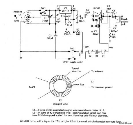
REGENERATIVE_RECEIVER_FOR_6_TO_17_MHz
Published:2009/6/24 4:49:00 Author:Jessie

The headphones are 32-Ω stereo types.The common lead is left floating so that the two sides are in series,giving 64Ω. (View)
View full Circuit Diagram | Comments | Reading(3095)
TWO_BAND_RADIO
Published:2009/6/24 4:25:00 Author:May
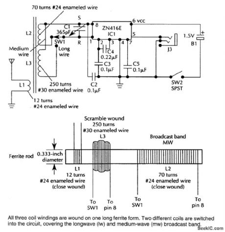
This TRF receiver covers the AM broadcast band and longwave bands (used in Europe and Asia for broadcasting). A loop antenna is used for reception and an extemal antenna can be connected.Frequency coverage is 150 to 1600 kHz. (View)
View full Circuit Diagram | Comments | Reading(0)
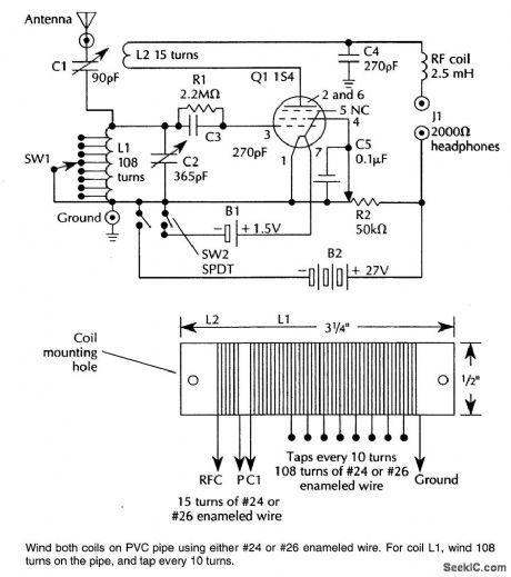
TOROIDAL_CORE_TRF_SHORTWAVE_RECEIVER
Published:2009/6/24 4:45:00 Author:Jessie
A ZN414 IC feeds an LM386 audio amplifier in this TRF circuit SW1is a band-switch,Coverageis up to 18 MHz. (View)
View full Circuit Diagram | Comments | Reading(4587)
ACTIVE_BASS_AND_TREBLE_TONE_CONTROL
Published:2009/6/24 4:41:00 Author:Jessie

A single transistor used as a feedback amplifier is connected with ac feedback through the tone controls, which determine the frequency response of the stage. (View)
View full Circuit Diagram | Comments | Reading(1642)
ONE_TUBE_REGENERATIVE_AM_RECEIVER
Published:2009/6/24 4:24:00 Author:May
Suitable for AM reception and as a simple radio project, this circuit uses a single tube as a regenerative detector. (View)
View full Circuit Diagram | Comments | Reading(0)
COMBINED_BASS_AND_TREBLE_CONTROL
Published:2009/6/24 4:41:00 Author:Jessie

This positive tone control system uses two pots to control bass and treble. (View)
View full Circuit Diagram | Comments | Reading(586)
BASS_TONE_CONTROL_CIRCUIT
Published:2009/6/24 4:40:00 Author:Jessie

This tone control has an insertion loss of 20 dB at flat setting and is effective below 350 Hz. The control has little effect above this frequency. (View)
View full Circuit Diagram | Comments | Reading(819)
IMPROVED_THERMOSTATIC_RELAY_CIRCUIT
Published:2009/6/24 4:24:00 Author:May

View full Circuit Diagram | Comments | Reading(568)
TREBLE_CONTROL_CIRCUIT
Published:2009/6/24 4:40:00 Author:Jessie

This tone control has an insertion loss of 20 dB at flat setting and is effective above 1 kHz,It little effect below about 1 kHz. (View)
View full Circuit Diagram | Comments | Reading(980)
FULL_RANGE_FAHRENHEIT_TEMPERATURE_SENSOR
Published:2009/6/24 4:24:00 Author:May

View full Circuit Diagram | Comments | Reading(865)
SPEED_SWITCH
Published:2009/6/24 4:24:00 Author:May

View full Circuit Diagram | Comments | Reading(1059)
LONG_PERIOD_TIMER
Published:2009/6/24 4:38:00 Author:Jessie

Adding a transistor to the 555 timer can create long timer periods, which is a key factor when the timer is operating at low speed. The transistor basically acts as a current divider or capacitance multiplier. The problem with low speed, however, is that the timing resistors and capacitors must be large and the charging current must be small, particularly when the desired timirtg period is in the range of seconds.
Typically, electrolytic capacitors are used in these situations, but their leakage current tends to aggravate or even prohibit operation at very low charging currents.This problem can be solved by adding a transistor. In effect, the transistor is used as a current divider or a capacitance multiplier. The normal charging current (emitter current) is divided by the transistor's current gain so that the capacitor charging current (base current) is reduced consider-ably. For example, 10μA of emitter current will require approximately 0.1 μA of base current, based on a current gain of 100.
In this circuit, the capacitor will be charged with such a low charging current that timing periods will typically be 100 times longer than usual. This means that substantial time periods can be achieved with film or ceramic capacitors that have much better leakage characteristics and are physically smaller.
The circuit's output pgriod was approximately 6 seconds, compared to 80 ms without the transistor. The transistor multiplied the normal time period by a factor of approximately 75. (View)
View full Circuit Diagram | Comments | Reading(2325)
PRECISION_RTD_AMPLIFIER_CIRCUIT_FOR+5_V
Published:2009/6/24 4:23:00 Author:May
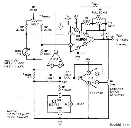
This circuit uses a platinum resistance temperature device to sense temperature. It has a range of 0 to 300℃. The RTD bridge is driven with a regulated 200-μA current to minimize self heating of the RTD. A 5-V supply is used. (View)
View full Circuit Diagram | Comments | Reading(913)
RECEIVER_PREAMP
Published:2009/6/24 4:37:00 Author:Jessie
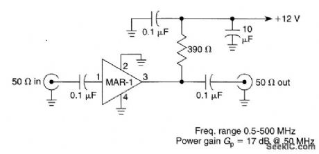
Suitable for HF and VHF receivers, this preamplifier can be mounted on the back of the receiver for a boost in gain. Useful gain is about 17 dB at 50 MHz (View)
View full Circuit Diagram | Comments | Reading(0)
SUPERHET_FRONT_END
Published:2009/6/24 4:36:00 Author:Jessie

This superhet receiver front end is simple and uses an NE602 followed by an MC1350 IF amplifier. (View)
View full Circuit Diagram | Comments | Reading(5754)
ONE_TUBE_REGENERATIVE_SW_RECEIVER
Published:2009/6/24 4:23:00 Author:May

A 154 tube is used in a regenerative detector circuit. Details for coils are shown and frequency range can be shifted within 1.5 to 20 MHz by proportionally adjusting the number of tums on coils (View)
View full Circuit Diagram | Comments | Reading(1024)
LAMP_TIMER
Published:2009/6/24 4:35:00 Author:Jessie
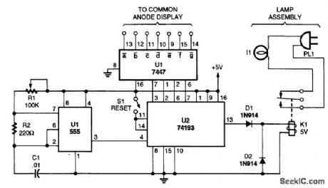

A timed switch uses a 555 oscillator/timer wired to operate in the astable mode. The timer sup-plies a positive pulse to the clock input of a 74193 4-bit binary up/down count every five minutes. Be-cause the 74193 is set to operate in the count-down mode, the output of the 555 is connected to the count-down input of the 74193.As the binary counter is reset, it starts counting at nine and counts down to zero with each clock pulse. When the counter hits zero, the output from the 74193 goes low, tuming off the relay and the light. The light can be tumed back on by pressing the reset button again. (View)
View full Circuit Diagram | Comments | Reading(0)
BALANCED_LINE_RECEIVER
Published:2009/6/24 4:34:00 Author:Jessie

Unity-gain inverter U2 drives R4 (usually grounded at -Vout, equalizing currents in tinput legs, and provides a choice of balanced p-p output with a gain of R2/R1). (View)
View full Circuit Diagram | Comments | Reading(1656)
AUTO_BATTERY_CURRENT_ANALYZER
Published:2009/6/24 4:23:00 Author:May

This op-amp analyzer can measure the current drawn by any device in a car. The analyzer works by measuring the very small voltage that develops across the battery cables when current flows. To calibrate the unit, mea-sure the current flow somewhere in the car with an accurate ammeter, then adjust the analyzer for that current reading. (View)
View full Circuit Diagram | Comments | Reading(678)
ALARM_CLOCK_TIMER
Published:2009/6/24 4:34:00 Author:Jessie

Turn your alarm clock into a specialized timer with this simple circuit. The clock used with the circuit should be the kind that turns on a little lamp when the alarm is activated. (View)
View full Circuit Diagram | Comments | Reading(1544)
| Pages:1337/2234 At 2013211322132313241325132613271328132913301331133213331334133513361337133813391340Under 20 |
Circuit Categories
power supply circuit
Amplifier Circuit
Basic Circuit
LED and Light Circuit
Sensor Circuit
Signal Processing
Electrical Equipment Circuit
Control Circuit
Remote Control Circuit
A/D-D/A Converter Circuit
Audio Circuit
Measuring and Test Circuit
Communication Circuit
Computer-Related Circuit
555 Circuit
Automotive Circuit
Repairing Circuit