Signal Processing
PRECISION_AUDIO_FREQUENCY_GENERATOR
Published:2009/6/24 21:25:00 Author:May | From:SeekIC


The precision audio-frequency generator consists of several subcircuits-an audio-amplifier/filter circuit, an automatic level control, a variable voltage-controlled oscillator, a frequency divider circuit, an integrator, and an audio output amplifier.
An electret microphone element is used to pick up the audio tone produced by the instrument. That signal is then fed to an amplifier/filter/level-controlled circuit and output via channel 1 (CH1) to an oscilloscope for display.
The variable voltage-controlled oscillator (VCO) is used to produce a signal offrom less than 10 kHz to more than 99 kHz. The VCO output is fed to a digital frequency counter for display, and is also routed to a chain of frequency dividers, where the signal is divided by 10, 100, or 1,000, depending on the setting of a selector switch.
From there, the selected signal frequency divides along two paths; one going to CH2 (which feeds the oscilloscope's sweep synchronization input) and to an integrator that converts the square-wave output of the divider into a triangular waveform. The output of the integrator is then amplified and fed to a set of stereo headphones via an audio output jack.
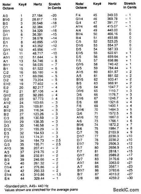
One section of the precision audio-frequency generator uses an electret microphone element to pick up audio from the piano. That signal is then processed and sent to one channel of a dual-trace oscilloscope. The other section of the circuit is used to produce a variable-frequency signal that is fed to a digital frequency counter and, after conditioning, is presented to the second channel of the scope and output to a set of stereo headphones.
Reprinted Url Of This Article:
http://www.seekic.com/circuit_diagram/Signal_Processing/PRECISION_AUDIO_FREQUENCY_GENERATOR.html
Print this Page | Comments | Reading(3)

Article Categories
power supply circuit
Amplifier Circuit
Basic Circuit
LED and Light Circuit
Sensor Circuit
Signal Processing
Electrical Equipment Circuit
Control Circuit
Remote Control Circuit
A/D-D/A Converter Circuit
Audio Circuit
Measuring and Test Circuit
Communication Circuit
Computer-Related Circuit
555 Circuit
Automotive Circuit
Repairing Circuit
Code: