
Index 54
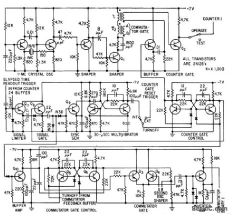
AUDITORIUM_ACOUSTICS_TIMER
Published:2009/7/23 22:28:00 Author:Jessie
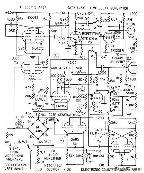
Can be set to accept any portion of incoming sound signal for feeding to electrostatic squarer and digital counter. Microphone preamp feeds gate input and trigger shaper. lime base consists of phantastron sawtooth generator and comparator giving delay time linearly variable from 0 to 120 millisec.-J. P. A. Lochner and P. Meffert, Electrostatic Squarer for Acoustic Measurements, Electronics, 33:35, p 66-68. (View)
View full Circuit Diagram | Comments | Reading(539)
Balanced_modulator_for_SSB_operation
Published:2009/7/23 22:41:00 Author:Jessie
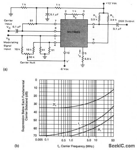
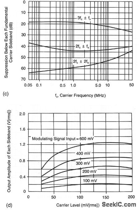
This circuit shows an MC1596 operating as a balanced modulator with +12-V and -8-V supplies. Recommended input signal levels are 60 mV (rms) for the carrier and 300 mV (rms) for the maximum modulating signal. Figures 2-42B and 2-42C show the suppression of carrier and sidebands, respectively. Figure 2-42D shows the sideband output levels. (View)
View full Circuit Diagram | Comments | Reading(752)
WATCH_TIMER
Published:2009/7/23 22:41:00 Author:Jessie
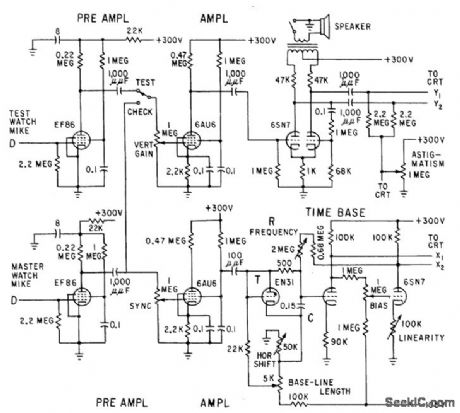
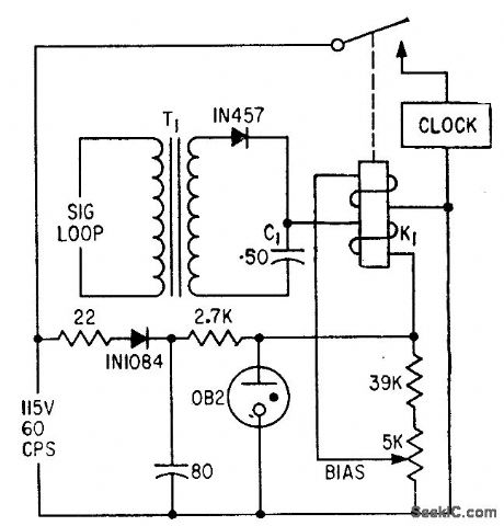
Simple time base, with high linearity, is achieved by two-stage d-c amplifier having unity gain, back-coupled to R.C integrator. Time-base reference, synchronized with master clock, can check accuracy of any timing device.-S. T. Kiewied, Watch Timer with Precise Time Base, Electronics, 31:51, p 84-85. (View)
View full Circuit Diagram | Comments | Reading(652)
Capacitance_multiplier
Published:2009/7/23 22:40:00 Author:Jessie

This circuit appears as a capacitance to the input. (View)
View full Circuit Diagram | Comments | Reading(0)
VHF_frequency_synthesizer
Published:2009/7/23 22:39:00 Author:Jessie
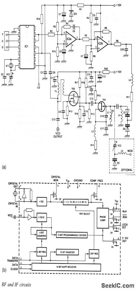
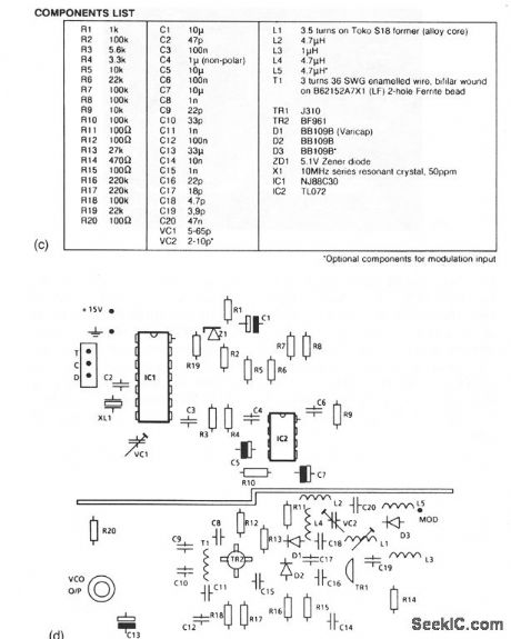
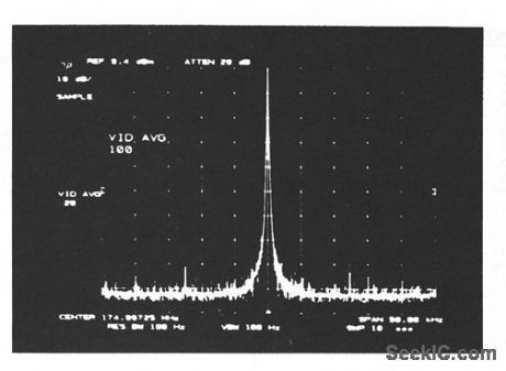
The NF88C30 shown in this circuit contains all the logic required for a high-band VHF PLL synthesizer. Figure 2-41 shows the internal circuits or the chip. The components list is shown in Fig. 2-41 C. As shown in the PC-board layout of Fig. 2-41D, the ground place is split between the VCO and synthesizer-control sections, with dc connections made via narrow tracks on either side of the board.This construction prevents synthesizer currents from causing spurious sidebands in the VCO output. The VCO can be modulated externally by adding L5, D3, and VC2. The output spectrum is shown in Fig. 2-41E. The output power is 9.4 dBm into 50Ω, with a frequency swing of about 10 MHz (from 170 to 1 80 MHz in this case). (View)
View full Circuit Diagram | Comments | Reading(1116)
Product_detector_for_SSB_operation
Published:2009/7/23 22:43:00 Author:Jessie

This circuit shows an MC1596 operating as a product detector with a single +12-V supply. The circuit can operate up to 100MHz. When operating in an SSB receiver with 50-Ω input impedance and an 0.5-μV RF input, 12-dB overall gain is required between antenna and the MC1596. Dual outputs (pins 6 and 9) can be used to drive the receiver audio amplifiers, and an AGC circuit, if desired. (View)
View full Circuit Diagram | Comments | Reading(1860)
INTERVALOMETER
Published:2009/7/23 22:43:00 Author:Jessie
Operates at end of pre determined period to produce second pre determined time period in range of 5 to 10 sec. Developed for medical electronic re search. Standby current is only 5 mc.-E. L. Dewig, Inexpensive UJT-SCR Intervalometer, EEE, 14:7, p 104. (View)
View full Circuit Diagram | Comments | Reading(991)
TELEPRINIER_CHARACTER_COUNTER
Published:2009/7/23 22:27:00 Author:Jessie
Simple circuit switches on timer dock only when teleprinter keying impulses are present, to give indication of traffic volume, low, and routing.-R. E. Pafenberg, Character Counter Aids Teletypewriter Routing, Electronics, 34:17, p 120-121. (View)
View full Circuit Diagram | Comments | Reading(658)
Single_balanced_mixer
Published:2009/7/23 22:27:00 Author:Jessie
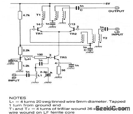
This circuit shows an SL2365 transistor array (Fig.2-35B) connected as a balance mixer, with a gain of 13 dB, a third-order incercept of -13 dB, and a noise figure of 10 dB. (View)
View full Circuit Diagram | Comments | Reading(704)
150__to_300_MHz_frequency_doubler
Published:2009/7/23 22:25:00 Author:Jessie
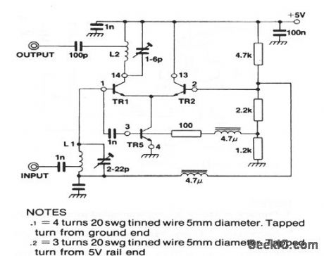
This circuit shows an SL2365 transistor array (Fig. 2-35B) connected as a frequency doubler, with a gain of +1 dB for a -20 dB input, and an input-frequency rejection of 18 dB. (View)
View full Circuit Diagram | Comments | Reading(647)
900_KC_FLAW_DETECTOR
Published:2009/7/23 22:24:00 Author:Jessie
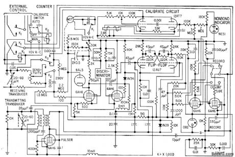
Attenuation of ultrasonic pulses boomed through test piece reveals presence and extent of internal defects, such as nonbonds between aluminum cladding and uranium core. Test piece and transducers are submerged in water to provide good coupling for 900-kc ultrasonic wave from barium titanate transducer of pulser. Motor sets discriminator threshold to equal signal received from attenuator.-J. D. Ross and R. W. Leep, Ultrasonic Pulses Detect Reactor-Slug Flaws, Electronics, 31:25, p 59-61. (View)
View full Circuit Diagram | Comments | Reading(1069)
SOLID_STATE_TIMER
Published:2009/7/23 22:24:00 Author:Jessie
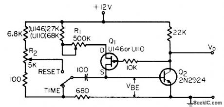
Uses fet constant-current source to eliminate timing errors due to unregulated power supplies and line transients. Range of 0.1 to 50 sec is con trolled by R2.-J. Geekie, Simple Fet Timer, EEE, 14:3, p 62. (View)
View full Circuit Diagram | Comments | Reading(691)
SONAR_PEAK_AMPLITUDE_DETECTOR
Published:2009/7/23 22:33:00 Author:Jessie
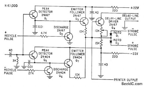
Reshapes pulses from playback amplifiers handling pulse-amplitude-modulation timedivision multiplex signals recorded and reproduced in magnetic-tape storage system, to provide narrow 2-microsec pulses coinciding with reference playback dock and having amplitude proportional to peak amplitude of input pulse sample. Used in training sonar operators at land-based sonar.-M. H. Damon, Jr., Tape Target Classifier Trains Sonar Operators, Electronics, 33:13, p 65-69. (View)
View full Circuit Diagram | Comments | Reading(654)
DUAL_OUTPUT_FREE_RUNNING_TIMER
Published:2009/7/23 22:33:00 Author:Jessie
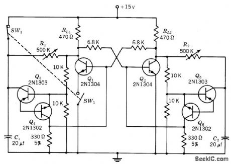
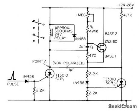
Each output may be controlled separately. With stable power-supply voltage and constant ambient temperature, accuracy of 0.1% may be expected with this type of repeating timer. Switch is shown in off position, Load resistors RL1 and RL2 can be replaced with 500-ohm relay coil shunted by 1N2069 diode. -Texas Instruments Inc., Transistor Circuit Design, McGraw-Hill, N.Y., 1963, p 414. (View)
View full Circuit Diagram | Comments | Reading(623)
VOLTAGE_CONTROLLED_RAMP_TRIGOER
Published:2009/7/23 22:37:00 Author:Jessie
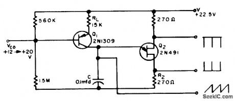
Provides ramp output with or without positive and negative trigger pulses over 6:1 linear range of frequency control. For values of C from 0.001 to 10 mfd, frequency range is 10 cps to 20 kc.-M. S. Tatch, Voltage-Controlled Ramp/Trigger Generator, FEE, 12:3, p 71. (View)
View full Circuit Diagram | Comments | Reading(568)
ENCODER_OSCILLATOR
Published:2009/7/23 22:37:00 Author:Jessie
Used to trigger 24 elapsed-time counters until end of storage period, for storing and reading out elapsed time between consecutive but randomly occurring events. Gates are designed to maintain amplitude of trigger pulse above half the supply voltage over wide temperature range.-R. J. Kelso and J. C. Groce, Encoder Measures Random Event Time Intervals, Electronics, 32:12, p 48-51. (View)
View full Circuit Diagram | Comments | Reading(602)
195_KC_SONAR_F_M_MODULATOR
Published:2009/7/23 22:53:00 Author:Jessie
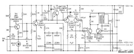
Used in recording signals from active sonar on magnetic tape, for later playback to control land-based sonar used in training operators. Modulator is basically sawtooth generator whose repetition frequency is changed by amplitude of modulating input signal.-M. H. Damon, Jr., Tape Target Classifier Trains Sonar Operators, Electronics, 33:13, p 65-69. (View)
View full Circuit Diagram | Comments | Reading(492)
100_W_25_KC_ULTRASONIC_GENERATOR
Published:2009/7/23 22:50:00 Author:Jessie
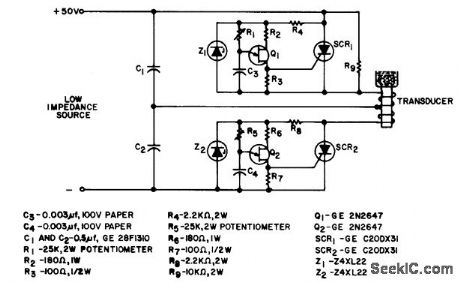
Frequency-doubling mode permits use of inexpensive scr's. Load resistance is in magnetostrictive transducer winding L. Circuit is actually 25-kc inverter triggered at 12.5-kc repetition rate.- Silicon Controlled Rectifier Manual, Third Edition, General Electric Co., 1964, p 16 (View)
View full Circuit Diagram | Comments | Reading(2503)
Double_balanced_mixer
Published:2009/7/23 22:45:00 Author:Jessie
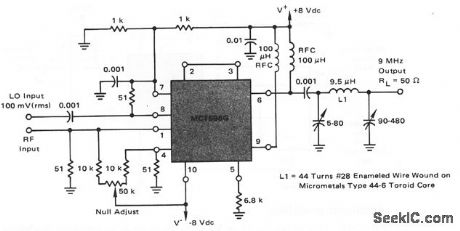
This circuit shows an MC1596 operating as a high-frequency mixer with a broadband input and a tuned output at 9 MHz. The 3-dB bandwidth of the 9-MHz output tank is 450 kHz. The local-oscillator (LO) signal of 100 mV is injected at pin 8, and the modulated-RF input of about 15 mV is injected at pin 1.For a 30-MHz input (pin 1) and a 39-MHz LO (pin 8), the mixer circuit has a conversion gain of 13 dB and an input sensitivity of 7.5μV for a 10 dB (S+N)/N ratio in the 9-MHz output signal. (View)
View full Circuit Diagram | Comments | Reading(0)
FIVE_SILICON_TRANSISTORS_BUILD_15_MV_SIGNAL_210_V_AT_5_W
Published:2009/7/23 23:16:00 Author:Jessie

Nulling amplifier energizes control winding of servomotor for error-signal inputs of only few millivolts, using two voltage amplifiers, driver, and push-pull power output stage.-C. H. Smoot and F. J. Karlov, Boiler Control: Simple Controller for a Complex Job, Electronics, 37:18, p 88-93. (View)
View full Circuit Diagram | Comments | Reading(2110)
| Pages:54/126 At 204142434445464748495051525354555657585960Under 20 |
Circuit Categories
power supply circuit
Amplifier Circuit
Basic Circuit
LED and Light Circuit
Sensor Circuit
Signal Processing
Electrical Equipment Circuit
Control Circuit
Remote Control Circuit
A/D-D/A Converter Circuit
Audio Circuit
Measuring and Test Circuit
Communication Circuit
Computer-Related Circuit
555 Circuit
Automotive Circuit
Repairing Circuit