
Index 53
FENCING_TOUCH_TIMER
Published:2009/7/23 22:20:00 Author:Jessie
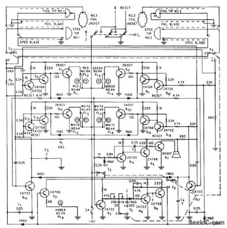
Detects touches in either epee or foil fencing, determines if touch is held long enough to score point, then starts timing interval in which other fencer may also score. Lamps indicate status of match. Loudspeaker sounds tone when sequence of touches is correct, and switch S1 must then be reset for next scoring sequence.-W. R. Durrell, Electronic Judging of Fast-Moving Sports Contests, Electronics, 32:32, p 114-115. (View)
View full Circuit Diagram | Comments | Reading(1640)
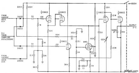
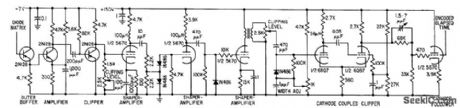
TWO_WAY_SAMPLING_SWITCH
Published:2009/7/23 22:20:00 Author:Jessie
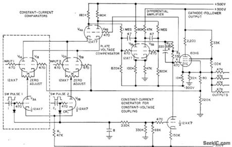
Uses two compensated comparators V1 and V2 whose currents are maintained constant by V3A and V3B, while V4 maintains constant plate voltage on these tubes. May be expanded to multi-way unit by adding input selector circuits, or may be used as precision cathode follower by eliminating selector. Circuit has near-infinite input impedance and near-zero output impedance. Comparator compensation permits accuracy of 0.1% over range of -100 to +100 V.-R. Benjamin, Electronic Switch Doubles as Cathode Follower, Electronics, 31:3, p 81-83. (View)
View full Circuit Diagram | Comments | Reading(686)
IMPROVED_THYPATRON_TIMER
Published:2009/7/23 22:19:00 Author:Jessie
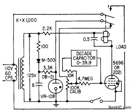
Linearity is improved by varying capacitance rather than resistance in grid circuits. riming error is less than 1% for 1 to 400 sec.-R. L. Ives, Timer Made More Linear, Electronics, 32:5, p 66-69. (View)
View full Circuit Diagram | Comments | Reading(514)
10_SEC_SCS_TIMER
Published:2009/7/23 22:24:00 Author:Jessie
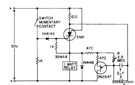
Switch applies positive pulse to gate of scs, triggering it on and thereby supplying power to relay load and ujt timing circuit. At end of timing interval, determined by R-C, timer feeds negative pulse to anode to turn off scs.- Transistor Manual, Seventh Edition, General Electric Co., 1964, p 435. (View)
View full Circuit Diagram | Comments | Reading(1327)
MAGNETIC_FILM
Published:2009/7/23 22:23:00 Author:Jessie
Circuit subtracts one sampled waveform from the next, to reduce noise disturbances by factor of 10 in equipment using strip transmission line for determining polarity reversal time of thin magnetic films to be used as switching elements in computers.-W. Dietrich and W. E. Proebster, Measuring Switching Speed of Magnetic Films, Electronics, 33:23, p 79-81. (View)
View full Circuit Diagram | Comments | Reading(511)
LINEAR_SCALE_FET_TIMER
Published:2009/7/23 22:23:00 Author:Jessie
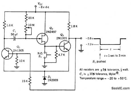
Operation com pares to that of one-shol mvbr.Q3 is normally on and C1 is charged. When S1 is closed, Q2 and Q3 turn off. Q3 remains off until charge on C1 decreases to point where Q2 is turned on sufficiently to make Q3 con duct, Q2 here acts as voltage-variable re sistor.-Texas Instruments Inc., Transistor Circuit Design, McGraw-Hill, N.Y., 1963, p 519. (View)
View full Circuit Diagram | Comments | Reading(621)
HEIGHT_SAMPLING_GIVES_NANOSECOND_RESOLUTION
Published:2009/7/23 22:21:00 Author:Jessie
Eight identical four-transistor difference ampli0ers in parallel divide input signal into eight levels for sampling. In each, input signal is compared to reference signal in Q2-Q3.-A. A. Fleischer and E. Johnson, New Digital Conversion Method Provides Nanosecond Resolution, Electronics, 36:18, p 55-57. (View)
View full Circuit Diagram | Comments | Reading(583)
BROADBAND_HYDROPHONE_PREAMP
Published:2009/7/23 22:36:00 Author:Jessie
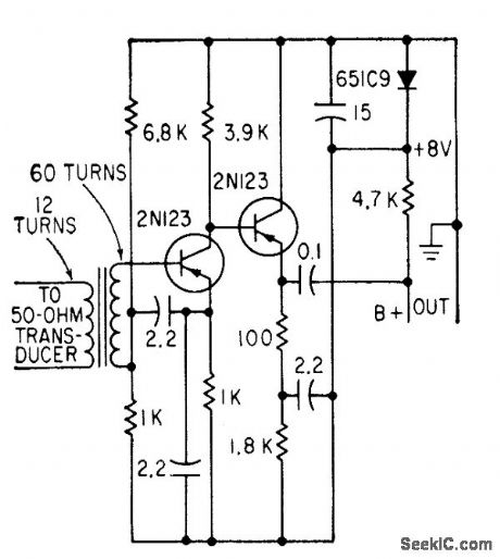
Provides gain of 35 db at 250 kc, with extremely low noise figure (within 1 db of thermal). Operating power of 20 ma d-c can be fed down same RG/8 coax used to transmit signal-R. N. Foss, Transistor Preamp has Very Low Noise, Electronics, 31:29, p 92-96. (View)
View full Circuit Diagram | Comments | Reading(682)
BASIC_HYBRID_UJT_NPN_TIMER
Published:2009/7/23 22:36:00 Author:Jessie
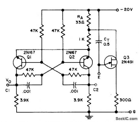
Serves as symmetrical square-wave mvbr when fixed or variable resistor is connected between E and G. Serves as one-shot mvbr when fixed or variable resistor is connected between C1 and E. Other external connections give con stunt or variable-frequency nonsymmetrical multivibrators.- Trcansistor Manual, Seventh Edition, General Electric Co., 1964, p 338. (View)
View full Circuit Diagram | Comments | Reading(602)
ENCODER_COMMUTATOR
Published:2009/7/23 22:35:00 Author:Jessie
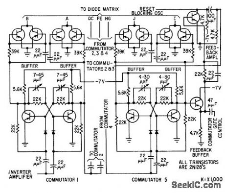
Commutator, buffer, und feedback circuits are given for elapsed-time encoder. After oscillator has triggered 24 elapsed-time counters during storage period, oscillator is switched to electronic commutator controlling diode matrix switch. Counter data is then read out serially through matrix and fed to crt for photo-graphing.-R. J. Kelso and J. C. Groce, Encoder Measures Random Event Time Intervals, Electronics, 32:12, p 48-51. (View)
View full Circuit Diagram | Comments | Reading(594)
RESPONDER_FOR_13_KC_DOG_WHISILE
Published:2009/7/23 22:35:00 Author:Jessie
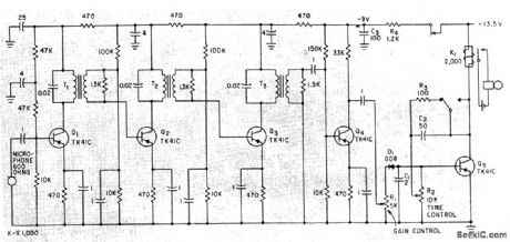
Tuned stages Q1-Q2-Q3 each having 700cps bandwidth, staggered to give total bandwidth of 1.7 kc for amplifier. Untuned stage Q4 maximizes gain yet prevents operation of device by circuit noise. Diode detector D1 makes Q5 conduct, energizing relay K1 and sounding response bell for 25 sec(controlled by charging of C3).-M. R. McGraw and I. Aleksander, Ultrasonic Frequency Responder Aids Blind, Electronics, 34:43, p 48-49. (View)
View full Circuit Diagram | Comments | Reading(517)
Serially_programmable_VHF_frequency_synthesizer_1
Published:2009/7/23 22:34:00 Author:Jessie
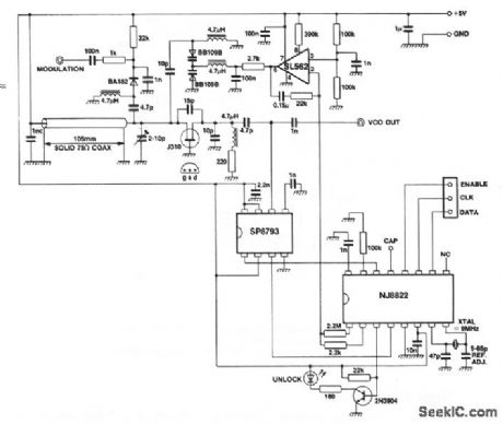
This circuit uses an NJ8822 single-chip synthesizer, an SP8793 dual-modulus prescaler, and an SL562 low-noise op amp to form a frequency synthesizer, with an output range from 144 to 146 MHz at a level of +3 dBm into 50Ω. The lock-up time for a 1-MHz change in frequency is 80 ms. The NJ8822 is programmed via a serial microprocessor interface. The VCO (using a coax resonator) is modulated by applying audio to the cathode of a reverse-biased PIN diode. The loop filter uses the SL562, which has a loop bandwidth of 60 Hz (with the values shown) and a damping factor of 0.6. The filter is followed by a low-pass pole at 3.7 kHz to attenuate the 12.5-kHz reference sidebands. (View)
View full Circuit Diagram | Comments | Reading(1179)
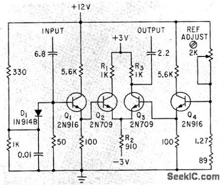
195_KC_SONAR_F_M_DEMODULATOR
Published:2009/7/23 22:28:00 Author:Jessie
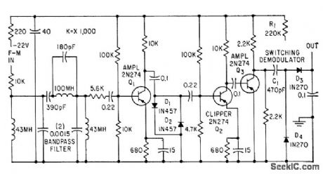
Used in playback of active sonar f-m signals multiplexed onto one track of magnetic tape, for training students at land-based sonar. Bandpass fiber at input demodulator selects band of frequencies associated with desired f-m terrier. Output from filter is amplified and dipped for switching demodulator, whose output is varying component of average modulating signal current.-M. H. Damon, Jr., Tape Target Classifier Trains Sonar Operators, Electronics, 33:13, p 65-69. (View)
View full Circuit Diagram | Comments | Reading(624)
WATER_DEPTH_TELEMETER
Published:2009/7/23 22:26:00 Author:Jessie
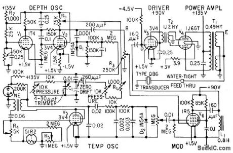
Determines exact depth of trawl net under water, for interception of desired school of fish. Continuous depth information is transmitted to trawler by modulated 21-kc ultrasonic beam, along with water temperature.-F. H. Stephens, Jr., Underwater Telemeter for Trawl Fishing, Electronics, 32:13, p 66-68. (View)
View full Circuit Diagram | Comments | Reading(721)
22_KC_SONAR_1
Published:2009/7/23 22:48:00 Author:Jessie
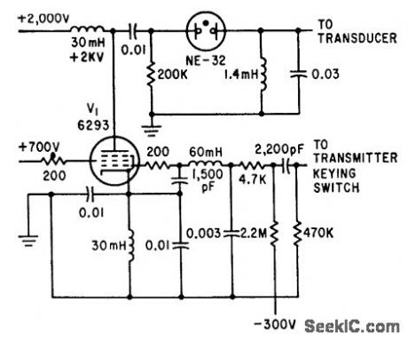
key pulse allows Clapp oscillator to operate for 1 millisec at 22 kc, with keying 25 times per second.-L. H. Dulberger, Sonar to Survey Arctic Ocean Shelf Transmits Through Ice and Water, Electronics, 34:31, p 44-45. (View)
View full Circuit Diagram | Comments | Reading(747)
150__to_300_MHz_frequency_doubler_1
Published:2009/7/23 22:48:00 Author:Jessie
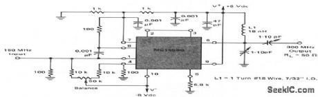
This circuit shows an MC1596 operating as a 150- to 300-MHz frequency doubler with suitable output filtering. All spurious outputs are 20 dB (or more) below the desired 300-MHz output. (View)
View full Circuit Diagram | Comments | Reading(626)
ENCODER_OUTPUT
Published:2009/7/23 22:44:00 Author:Jessie
Output circuits are given for encoder used in storing and reading out elapsed time between consecutive randomly occurring events. Cathode follower stage provides low output impedance to give desired output waveform on crt for showing encoded elapsed time.-R. J. Kelso and J. C. Groce, Encoder Measures Random Event Time Intervals, Electronics, 32:12, p 48-51. (View)
View full Circuit Diagram | Comments | Reading(518)
HIGH_CURRENT_SCS_INTERVAL_TIMER
Published:2009/7/23 22:31:00 Author:Jessie
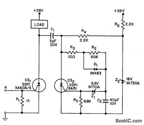
When triggered by low-level 5-microsec pulse, furnishes 1 amp to load for 1 sec. Advantages are simplicity and high reliability through use of silicon controlled switches.-Y. J. Lubkin, High Output Interval Timer, EEE, 10:9, p 92. (View)
View full Circuit Diagram | Comments | Reading(557)
UJT_INTERVAL_TIMER
Published:2009/7/23 22:30:00 Author:Jessie
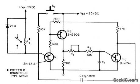
Inexpensive relay provides excellent timing accuracy and high isolation in circuit using power gain of emitter junction of ujt Q1. Timing is determined by R1, R2, and C1.-N. H. Kadivnik, Interval Timer, EEE, 12:5, p 75. (View)
View full Circuit Diagram | Comments | Reading(602)
200_MC_BINARY_FOR_INTERVAL_TIMER
Published:2009/7/23 22:29:00 Author:Jessie
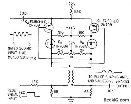
Gated 200-Mc input is fed to both emitters. Individual tenet diodes provide collector bias. Base bios is obtained from collector resistor load of opposite transistor. Potentiometer permits perfect balancing. Time intervals are measured accurately to 5 nsec.-C. S. Coffey, VHF Counter Measures Time Iptervals Precisely, Electronics, 36:34, p 27-29. (View)
View full Circuit Diagram | Comments | Reading(580)
| Pages:53/126 At 204142434445464748495051525354555657585960Under 20 |
Circuit Categories
power supply circuit
Amplifier Circuit
Basic Circuit
LED and Light Circuit
Sensor Circuit
Signal Processing
Electrical Equipment Circuit
Control Circuit
Remote Control Circuit
A/D-D/A Converter Circuit
Audio Circuit
Measuring and Test Circuit
Communication Circuit
Computer-Related Circuit
555 Circuit
Automotive Circuit
Repairing Circuit