
Index 56
PREFERRED_VIDEO_AMPLIFIER_CHAIN
Published:2009/7/23 23:10:00 Author:Jessie
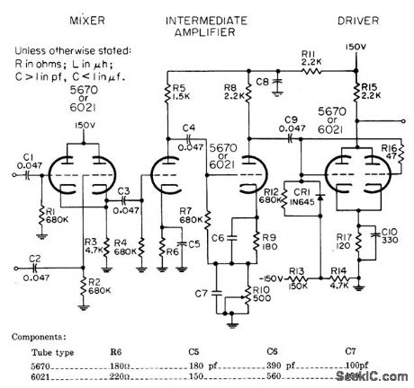
Designed for use in radar display system to mix positive radar video with positive marker pulses, to invert combined signals, and to amplify them sufficiently to intensity-modulate cathode-ray indicator. Input polarity is negative. Maximum peak amplitude is 60 v. Amplification is variable from 30 to 60.-NBS, Handbook Preferred Circuits Navy Aeronautical Electronic Equipment, Vol. I, Electron tube Circuits, 1963, PC 25, p 25-2. (View)
View full Circuit Diagram | Comments | Reading(661)
FLAT_TUBE_SCANNER
Published:2009/7/23 23:09:00 Author:Jessie
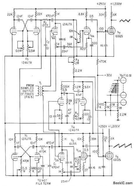
V1 thru V3 generate sawtooth wave and V5 thru V7 triangular wave for driving horizontal and vertical conductors of electroluminescent panel. -B. Binggeli and E. Fatuzzo, Solid-State Panels: Will They Bring Flat-Display TV? Electronics, 35:26, p 67-70. (View)
View full Circuit Diagram | Comments | Reading(757)
PREFERRED_BEAM_POWER_DRIVER
Published:2009/7/23 23:08:00 Author:Jessie
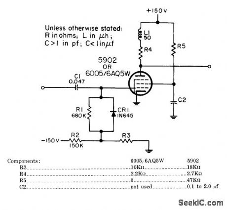
Used in search radars to amplify video signals to 60.v level required for intemsity modulation of cathode-ray indicator. Input polarity is positive. Amplification is 7.-NBS, Hand-book Preferred Circuits Navy Aeronautical Electronic Equipment, Vol. I, Electron Tube Circuits, 1963, PC 28, p 28-2.
(View)
View full Circuit Diagram | Comments | Reading(601)
TWO_PHOTOMULTIPLIER_SUBTRACTION_CIRCUIT
Published:2009/7/23 23:08:00 Author:Jessie
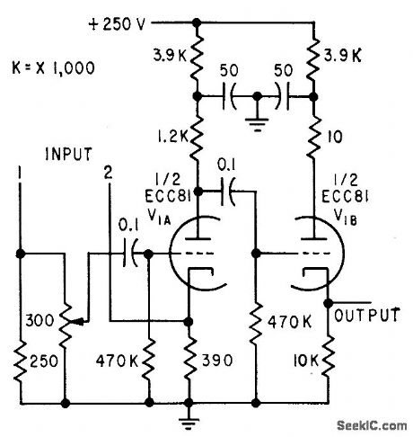
Flying-spot closed-circuit tv system compares two photographs and displays only differences between them, for automatic identification of variable stars. Both photo-multiplier signals are coupled to subtraction tube V1A. Difference signal is fed by cathode follower to video amplifier of 14-inch tv monitor.-J. Borgman, Using Tv Techniques in Astronomy, Electronics, 32:19, p 66-68. (View)
View full Circuit Diagram | Comments | Reading(718)
TWELVE_FREQUENCY_SERVO_TUNER
Published:2009/7/23 23:14:00 Author:Jessie
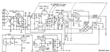
Negative feedback voltage proportional to servo speed is picked off winding of servomotor to improve stability in stopping at point of zero error voltage in output of 6AL5 frequency discriminator-K. Makino and T. Yamanaka, Servo-Tuned Transceiver for Airborne VHF Communications, Electronics, 35:1, p 82-85. (View)
View full Circuit Diagram | Comments | Reading(1129)
PUSH_PULL_CUPPER
Published:2009/7/23 23:13:00 Author:Jessie

Accepts balanced output of video preamp in microwave interferometer system and provides both linear and clipped outputs for oscilloscope.-H. L. Bunn Determining Electron Density and Distribution in Plasmas, Electronics, 34:14, p 71-75. (View)
View full Circuit Diagram | Comments | Reading(503)
TRANSDUCER_SCANNER_WITH_INDICATORS
Published:2009/7/23 23:12:00 Author:Jessie
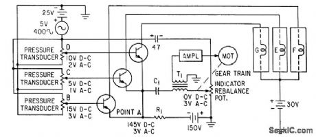
Transducers monitored in parallel mode actuate a-c servo when any one goes beyond predetermined range. Transistor then turns on lamp to identify transducer whose output has actuated the servo.-S. Thaler, Solid-Slate Parallel-Mode Scanner Reads System Physical Parameters, Electronics, 34:19, p 78-80. (View)
View full Circuit Diagram | Comments | Reading(580)
PUPILLOGRAPH
Published:2009/7/23 23:11:00 Author:Jessie
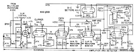
Measures movements of pupil of eye, using flying-spot scanning unit with multiplier phototube, amplifier-detector, and recorder.-G. W. King, Recording Pupil Changes For Clinical Diagnosis, Electronics,32:39, p 67-69. (View)
View full Circuit Diagram | Comments | Reading(747)
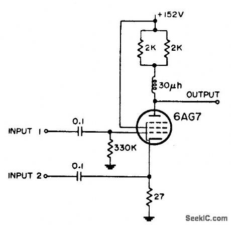
TRIPLE_INPUT_VIDEO_MIXER
Published:2009/7/23 23:11:00 Author:Jessie
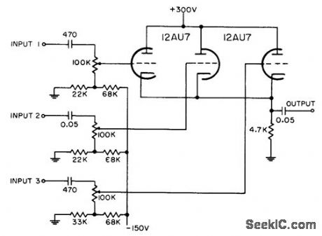
Each grid is biased to cutoff, so mixer accepts only positive-polarity pulses having sufficient amplitude to overcome this bias.-NBS, Handbook Preferred Circuits Navy Aeronautical Electronic Equipment, Vol. 1, Electron Tube Circuits, 1963, p N4-2. (View)
View full Circuit Diagram | Comments | Reading(778)
100_MC_BANDWIDTH_VIDEO_AMPLIFIER
Published:2009/7/23 23:11:00 Author:Jessie
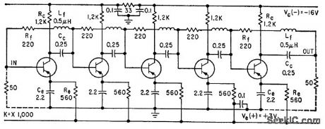
Shunt feedback networks around each stage reduce overall gain at low frequencies, trading gain for bandwidth, so that five cascaded stages give overall gain of 50 db.-J. C. de Broekert and R. M. Scarlett, Transistor Amplifier has 100 Megacycle Bandwidth, Electronics, 33:16, p 73-75. (View)
View full Circuit Diagram | Comments | Reading(526)
FET_SERVO_AMPLIFIER
Published:2009/7/23 23:55:00 Author:Jessie
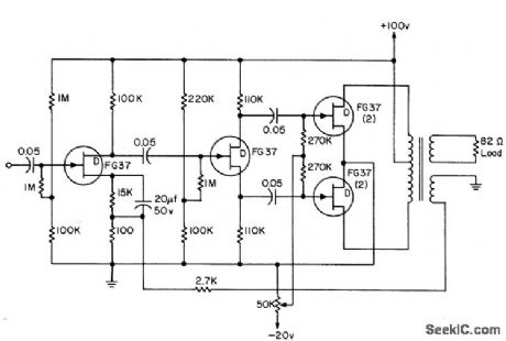
Servo amplifier uses medium-power fet's for 1.5 W output. Circuit has no driver transformer for power stage, and only one electrolytic. Power gain is 70 db, voltage amplification 30 db, input resistance 1 meg, and maximum efficiency 56%.-L. J. Sevin, J., Field-Effect Transistors, McGraw-Hill, N.Y., 1965, p 100. (View)
View full Circuit Diagram | Comments | Reading(2006)
STALLED_SERVO_MOTOR_SHUTOFF
Published:2009/7/23 23:54:00 Author:Jessie
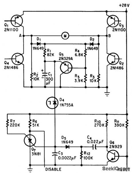
Silicon controlled switch Q7 in timing circuit turns on each time servo motor is actuated, and re moves power from motor if it remains on more than 15 sec, indicating a stall.-D. Perlman, Silicon Switch Turns Off Stalled Servo-motors, Electronics, 39:10, p 90-91. (View)
View full Circuit Diagram | Comments | Reading(573)
PREFERRED_AMPLIFICATION_70_PREAMPLIFIER
Published:2009/7/23 23:53:00 Author:Jessie
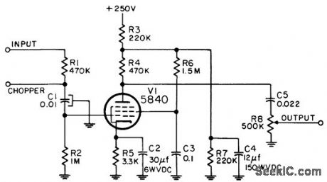
Used with instrument servo motor controller to increase available gain. Chopper is used with d-c inputs only. Frequency range is 380 to 420 cps.-NBS, Handbook Preferred Circuits Navy Aeronautical Electronic Equipment, Vol. I, Electron Tube Circuits, 1963, PC 72, p 72-2. (View)
View full Circuit Diagram | Comments | Reading(572)
Enable_and_disable_timing_tests
Published:2009/7/23 23:53:00 Author:Jessie
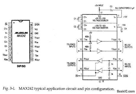
Figure 3-L shows the typical application circuit and pin configuration for the MAX242. This IC is similar to the MAX220, except that the receiver channels can be enabled and disabled, and all four channels can be shut down by external signals. Figures 3-M and 3-N show test circuits and waveforms for receiver-channel enable/disable, and transmitter-channel disable timing. (View)
View full Circuit Diagram | Comments | Reading(635)
PENTODE_MIXER
Published:2009/7/23 23:32:00 Author:Jessie
Negative video plus iff signals are inserted at grid, while range strobe, from cathode output of blocking oscillator, is applied to cathode.-NBS, Handbook Preferred Circuits Navy Aeronautical Electronic Equipment, Vol.1, Electron Tube Circuits, 1963, p N4-4. (View)
View full Circuit Diagram | Comments | Reading(657)
NONADDITIVE_COMMON_PLATE_MIXER
Published:2009/7/23 23:24:00 Author:Jessie
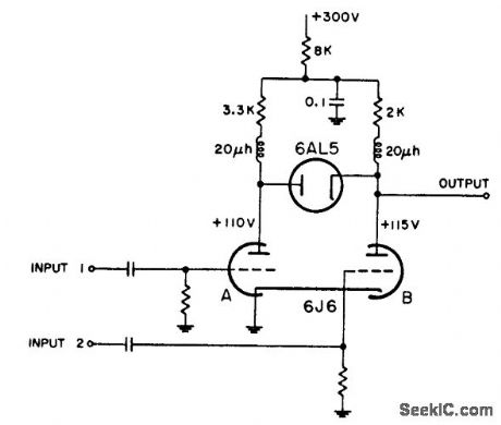
Plates ore coupled by diode that is nonconducting because plate is at lower potential than cathode. If input pulses are not coincident, negative pulse of sufficient amplitude at either input will appear at output. If inputs are coincident, positive pulse appearing at plate of section A will not appear at output unless of sufficient amplitude to overcome bias established by positive output from section B. Radar video must be applied to input 2, since output of section A must overcome 5-v diode bias,-NBS, Handbook Preferred Circuits Navy Aeronautical Electronic Equipment, Vol. 1, Electron Tube Circuits, 1963, p N4-4. (View)
View full Circuit Diagram | Comments | Reading(564)
6_W_HIGH_EFFICIENCY_AMPLIFIER
Published:2009/7/23 23:23:00 Author:Jessie
Overall efficiency is 55%. Design equations are given.-Texas Instruments Inc., Transistor Circuit Design, McGraw-Hill, N.Y., 1963, p 249. (View)
View full Circuit Diagram | Comments | Reading(629)
PREFERRED_LOW_LEVEL_COMMON_PLATE_MIXER
Published:2009/7/23 23:23:00 Author:Jessie
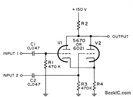
Combining of video signals with pulses is accompanied by inversion of input signal. Value of R4 is 270 ohms for 5670 and 470 ohms for 6021. R2 is 680 ohms for 5670 and 1 K for 6021. Input signals must be positive.-NBS, Handbook Preferred Circuits Navy Aeronautical Electronic Equipment, Vol. I, Electron Tube Circuits, 1963, PC 24, p 24-2. (View)
View full Circuit Diagram | Comments | Reading(2409)
THREE_INPUT_TWO_OUTPUT_MIXER
Published:2009/7/23 23:23:00 Author:Jessie
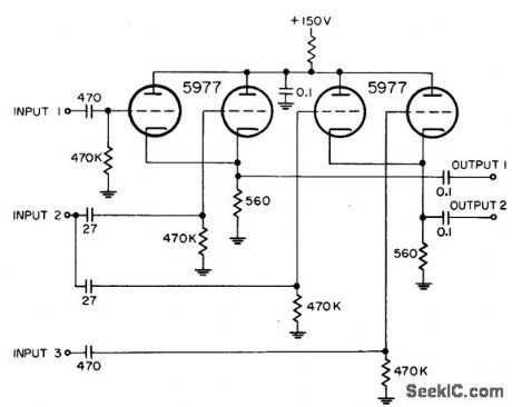
Uses two separate common-cathode video mixers. Same heading markers are inserted into both mixers front input 2, while other inputs handle independent markers.-NBS, Hand-book Preferred Circuits Navy Aeronautical Electronic Equipment, Vol.1, Electron Tube Circuits, 1963, p N4-3. (View)
View full Circuit Diagram | Comments | Reading(563)
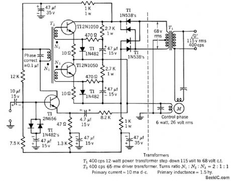
2_W_HIGH_EFFICIENCY_SERVO_AMPLIFIER
Published:2009/7/23 23:22:00 Author:Jessie
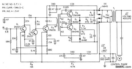
Voltage gain with feedback loop is 10,000, efficiency is above 50%, and gain changes less than 3 db between -55 and +125℃ .No center tap is required on control winding of moron-J. A. Walston and J. E. Setliff, Designing Servo Amplifiers for High Efficiency, Electronics, 3616, p 62-63. (View)
View full Circuit Diagram | Comments | Reading(566)
| Pages:56/126 At 204142434445464748495051525354555657585960Under 20 |
Circuit Categories
power supply circuit
Amplifier Circuit
Basic Circuit
LED and Light Circuit
Sensor Circuit
Signal Processing
Electrical Equipment Circuit
Control Circuit
Remote Control Circuit
A/D-D/A Converter Circuit
Audio Circuit
Measuring and Test Circuit
Communication Circuit
Computer-Related Circuit
555 Circuit
Automotive Circuit
Repairing Circuit