
Index 55
PREFERRED_VIDEO_DETECTOR
Published:2009/7/23 23:16:00 Author:Jessie
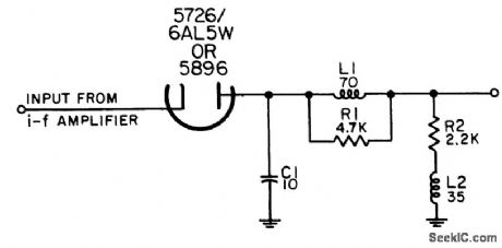
For demodulating pulse-modulated i-f signals in range between 20 and 70 Mc. Video output pulses ore negative, with 40 nsec rise time and 70 nsec fall lime.-NBS, Handbook Preferred Circuits Navy Aeronautical Electronic Equipment, Vol. 1, Electron Tube Circuits, 1963, PC 20, p 20-2. (View)
View full Circuit Diagram | Comments | Reading(574)
75_W_CLASS_B_SERVO_AMPLIFIER
Published:2009/7/23 23:15:00 Author:Jessie

Gives power gain of 45 db. Voltage amplification is constant within 2 db of 44 db. Transformer data is for 400-cps operation.-Texas Instruments Inc., Transistor Circuit Design, McGraw-Hill, N.Y., 1963, p 242. (View)
View full Circuit Diagram | Comments | Reading(640)
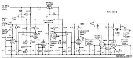
PARTIAL_ADDING_MIXER
Published:2009/7/23 23:14:00 Author:Jessie

Semiconductor diode connected between plates in nonconducting direction, with 1.5 v back voltage, reduces additive factor of common-plate mixer. Marker input must have sufficient amplitude to overcome diode back-bias before marker signal can appear at output. Positive radar video at input appears as negative output. At coincidence, radar video biases diode to extent that only small amount of marker pulse can pass and add to radar video.-NBS, Handbook Preferred Circuits Navy Aeronautical Electronic Equipment, Val. 1, Electron Tube Circuits, 1963, p N4-9. (View)
View full Circuit Diagram | Comments | Reading(541)
VIDEO_PREAMP
Published:2009/7/23 23:32:00 Author:Jessie

Accepts output of balanced mixer of microwave interferometer system. Bandwidth is 3 Mc.-H. L. Bunn, Determining Electron Density and Distribution in Plasmas, Electronics, 34:14, p 71-75. (View)
View full Circuit Diagram | Comments | Reading(2187)
SYNCHRONOUS_FILTER_FOR_ADF
Published:2009/7/23 23:31:00 Author:Jessie

Separates 130-cps motor drive voltage from voice frequencies in output of adf receiver-P. V. Sparks, Servo Filter and Gain Control Improve Automatic Direction Finder, Electronics, 34:23, p 110-113. (View)
View full Circuit Diagram | Comments | Reading(1601)
SHUNT_PEAKED_INTERSTAGE
Published:2009/7/23 23:31:00 Author:Jessie
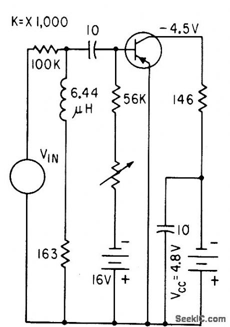
Pole-zero cancellation design procedure for using shunt peaking gives simple cascaded broadband video amplifier. Gain is 10.4 and bandwidth is 1.05 Mc.-R. 5. Pepper and D. O. Pederson, Designing Shunt-Peaked Transistor Amplifiers, Electronics, 33:49, p 68-70. (View)
View full Circuit Diagram | Comments | Reading(497)
TRANSFORMER_COUPLED_SERVO_AMPLIFIER
Published:2009/7/23 23:31:00 Author:Jessie
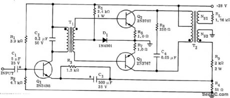
Three transistors provide stable voltage gain of 40 db and power gain of 37 db. Maximum output is 115 V rms into 1,760-ohm load, for 7.5 W.-N. Freyling, High Performance All Solid. State Servo Amplifiers, Motorola Application Note AN-225, Jan.1966. (View)
View full Circuit Diagram | Comments | Reading(713)
FOUR_INPUT_HIGH_LEVEL_PULSE_MIXER
Published:2009/7/23 23:30:00 Author:Jessie
Triode in series with plate load of mixer pro vides for additional blanking pulse.-NBS Handbook Preferred Circuits Navy Aeronoutical Electronic Equipment, Vol.1, Electron Tube Circuits, 1963, p N4-3. (View)
View full Circuit Diagram | Comments | Reading(595)
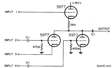
THREE_PENTODE_MIXER
Published:2009/7/23 23:30:00 Author:Jessie
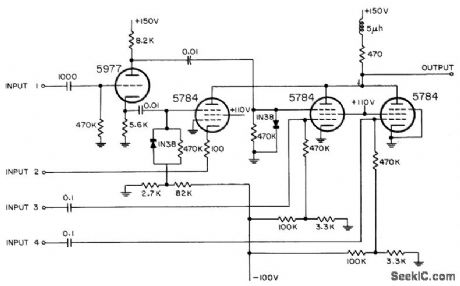
Triode is used as phase splitter. Both positive and negative signals are combined from four inputs. High-frequency compensation is used in common plate circuit of pentodes.-NBS, Handbook Preferred Circuits Navy Aeronautical Electronic Equipment, Vol. 1, Electron Tube Circuits, 1963, p N4-5. (View)
View full Circuit Diagram | Comments | Reading(559)
SERVO_AIMS_D_F_LOOP_AUTOMATICALLY
Published:2009/7/23 23:30:00 Author:Jessie
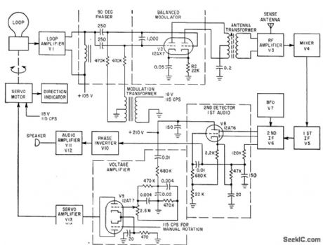
Bearing accuracy of 3 deg is obtained over frequency range of 190 kc to 2.8 Mc, Error-signals derived from balanced modulator and sense antenna are mixed, amplified, defected by V8, and amplified to drive two-phase antenna motor-L. D. Shergalis, Pleasure Boat Electronics Stresses Low Power Consumption, Operating Simplicity, Electronics, 35:4, p 20-21. (View)
View full Circuit Diagram | Comments | Reading(756)
VERTICAL_LOCATOR_FOR_CHARACTER_READER
Published:2009/7/23 23:03:00 Author:Jessie
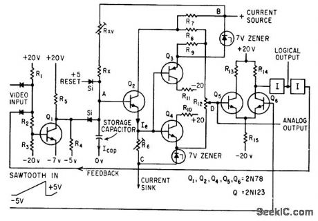
Sawtooth input is compared with earliest video of each vertical sweep of typed character being scanned, to charge capacitor and derive logical output related to bottom of typed line.-J. Bauldreay and E. Milbradt, Solving Registration Problems in Optical Character Recognition, Electronics, 35:1, p 77-81. (View)
View full Circuit Diagram | Comments | Reading(576)
UJT_RASTER_GENERATOR
Published:2009/7/23 23:02:00 Author:Jessie
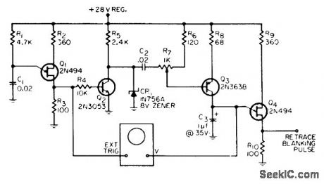
Developed for use in low-cost transistorized flying-spot scanner. Can also be adapted for closed-circuit tv cam eras and monitors. Ujt Q1 is relaxation oscillator at desired horizontal sweep rate of 10 kc. Interlaced scanning is easily obtained.-F. Stevens, Low-Cost UJT Raster Generator, EEE, 13:12, p 65-66. (View)
View full Circuit Diagram | Comments | Reading(833)
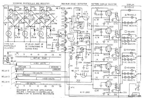
NUCLEAR_TRACK_COUNTER
Published:2009/7/23 23:01:00 Author:Jessie
Recognition system scans nuclear emulsion strips coated on glass, using image orthicon with microscope. Straight or moderately curved tracks in emulsion, produced by nuclear particles, are recognized and counted by scanner that used video screening circuit shown. Opaque emulsion regions thee meet narrowness criteria produce output pulses.-P. V. C. Hough, J. A. Koenig, and W. Williams, Stunner Recognizes Atomic Particle Tracks, Electronics, 32:13, p 58-61. (View)
View full Circuit Diagram | Comments | Reading(847)
STABILIZING_PHOTOMULTIPLIER_GAIN
Published:2009/7/23 23:07:00 Author:Jessie
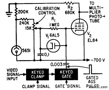
Feed-back loop provides automatic gain stabilization for color film scanner.-R. M. Farber and K. M. St. John, Scanner Analyzes Color Content of Movie Film, Electronics, 34:48, p 38-41. (View)
View full Circuit Diagram | Comments | Reading(624)
PREFERRED_LOW_LEVEL_AMPLIFIER
Published:2009/7/23 23:06:00 Author:Jessie
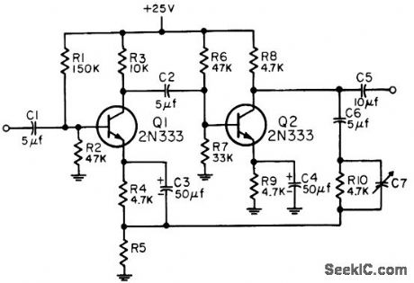
Serves as high-gain amplifier providing stable gain over wide temperature range, with maximum output of 2 v. Is noninverting, has input impedance of 20,000 ohms, and will operate into loads above 10,000 ohms. Several circuits may be cascaded. 2N333 has been dropped front Preferred list, but 2N335 can be used if operating point is adjusted for its larger beta. Voltage gains of 45, 20, or 10 ore obtained for R5 = 100, 220, and 470 ohms respectively.-NBS, Handbook Preferred Circuits Navy Aeronautical Electronic Equipment, Vol. II, Semiconductor Device Circuits, PSC 18 (originally PC 201), p 18-2. (View)
View full Circuit Diagram | Comments | Reading(626)
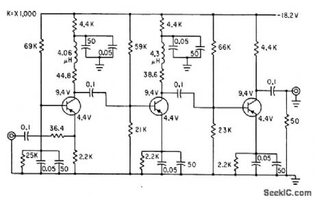
WIDEBAND_VIDEO_AMPLIFIER
Published:2009/7/23 23:06:00 Author:Jessie
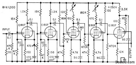
Has gain of 1,000, bringing 1-mV input up to 1 V. First two stages are cathode-bypassed, and next two use inductive compensation for high-frequency peaking, to compensate for non infinitesimal short persistence of screen of flying-spot scanner. Used in comparing two sky photographs to detect variable stets.-J. Borgman, Using Tv Techniques in Astron. omy, Electronics, 32:19, p 66-68. (View)
View full Circuit Diagram | Comments | Reading(499)
SILICON_WIDEBAND_VIDEO_AMPLIFIER
Published:2009/7/23 23:05:00 Author:Jessie
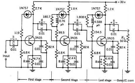
Employs feedback around each of its three stages, with zener diode for stabilizing collector. emitter voltage. Voltage and current amplification are 20 db, and useful frequency range is 3.2 kc to 32 Mc,-Texas Instruments Inc., Transistor Circuit Design, McGraw-Hill, N.Y., 1963, p 267. (View)
View full Circuit Diagram | Comments | Reading(730)
SHAPE_RECOGNITION
Published:2009/7/23 23:05:00 Author:Jessie
Use of dilating circular scan resolves some of problems for general-purpose reading machine. Technique can be applied to automatic recognition of letters and numbers in variety of styles.-L. D. Harmon, Line-Drawing Pattern Recognizer, Electronics, 33:36, p 39-43. (View)
View full Circuit Diagram | Comments | Reading(671)
CASCADED_SHUNT_PEAKED_STAGES
Published:2009/7/23 23:04:00 Author:Jessie
Design procedure is given for n identical one-pole stages. Bandwidth of total cascaded amplifier is equal to bandwidth of single stage multiplied by shrinkage factor of 0.64 for two stages, 0.51 for three, and 0.44 for four. two stage example shown gives gain of 8.5 and bandwidth of 2.1 Mc.-R. S. Pepper and D. O. Pederson, Designing Shunt-Peaked Transistor Amplifiers, Electronics.33:49, p 68-70. (View)
View full Circuit Diagram | Comments | Reading(1450)
FLYING_SPOT_SCANNER_PROTECTS_MICRO_FILM
Published:2009/7/23 23:10:00 Author:Jessie
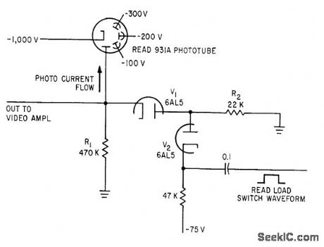
When black mark on microfilm covers quiescent spot, sweep is tripped and rectangular pulse on cathode of V2 cuts it off. 931A multiplier phototube then sees 22,000-ohm load through V1 to give correct output.-A. C. L. Brown, Flying Spot Inspects Tv Rating Records, Electronics, 35;9, p 31-34. (View)
View full Circuit Diagram | Comments | Reading(610)
| Pages:55/126 At 204142434445464748495051525354555657585960Under 20 |
Circuit Categories
power supply circuit
Amplifier Circuit
Basic Circuit
LED and Light Circuit
Sensor Circuit
Signal Processing
Electrical Equipment Circuit
Control Circuit
Remote Control Circuit
A/D-D/A Converter Circuit
Audio Circuit
Measuring and Test Circuit
Communication Circuit
Computer-Related Circuit
555 Circuit
Automotive Circuit
Repairing Circuit