
Index 52
PLUG_IN_TOOL_USE_TIMER
Published:2009/7/23 22:14:00 Author:Jessie
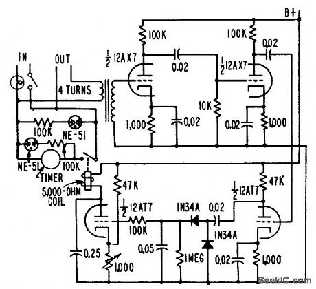
Serves as running time meter for soldering suns, electric drills, and other portable power tools. Tool is plugged into outlet on timer, eliminating need for connections lo switch of device under test. Load capacity is from 25 to 1,000 w. R. L. lves, Circuit Times Operation of Portable Tools, Electronics, 31:5, p 62-64. (View)
View full Circuit Diagram | Comments | Reading(542)
22_KC_SONAR
Published:2009/7/23 22:14:00 Author:Jessie
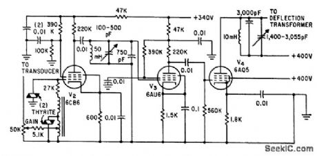
Amplifier is coupled to sonar transducer through 8:1 step-up transformer and resistor-varistor network. Circuit feeds cathode-ray display that protects V2 from overload and possible blocking during echo return time. Receiver gain is 137 db.-L. H. Dulberger, Sonar to Survey Arctic Ocean Shelf Transmits Through Ice and Water, Electronics, 34;31, p 44-45. (View)
View full Circuit Diagram | Comments | Reading(1104)
CMOS_RE_video_multiplexer
Published:2009/7/23 22:13:00 Author:Jessie

Figure 2-10 shows a typical application circuit and pin configurations for the MAX310/11. The key feature of the IC is extremely high off-isolation at high frequencies. The isolation of each off channel to the output is guaranteed to be -66 dB at 5 MHz. The input signal range is +12 V to -15 V with t15-V supplies.Power consumption is typically 1.1mW. All control inputs are fully compatible with TTL and CMOS. Decoding is in standard BCD. An enable input is provided to simplify cascading of the ICs. The ICs will operate with power supply combinations that total less than 36 V (V+ - V-), including single-supply operation at +12 V, +15-V, and +28 V with V- connected to ground. MAXIM HIGH-RELIABILITY DATA Book, 1993, P. 1-1. (View)
View full Circuit Diagram | Comments | Reading(589)
BASIC_HYBRID_UJT_PNP_TIMER
Published:2009/7/23 22:13:00 Author:Jessie
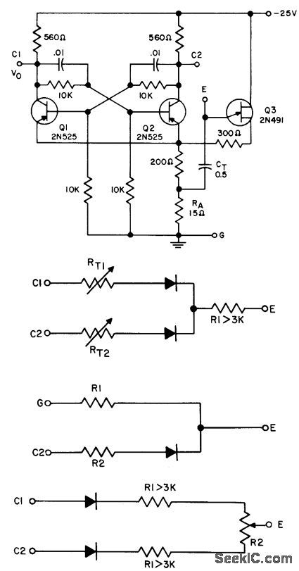
Serves as symmetrical square-wave mvbr when fixed or variable resistor is connected between E and G. Serves as one-hot mvbr when fixed or variable resistor is connected between C1 and E. Other configurations shown for external connections give constant or variable-frequency nonsymmetrical multivibrators.- Transistor Manual, Seventh Edition, General Electric Co., 1964, p 338. (View)
View full Circuit Diagram | Comments | Reading(577)
HYDROPHONE_PREAMP
Published:2009/7/23 22:13:00 Author:Jessie
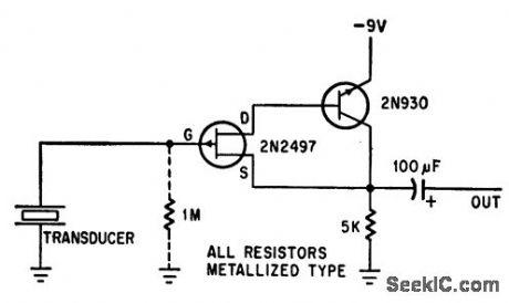
Fet eliminates unwanted noise and added capacitance caused by long cobias connecting hydrophone to shore station, Voltage gain is unity. Can be used with cables UP to 3.000 feel long. if hydrophone moves in water, use 1-meg resistor between gate and ground to suppress low-frequency excursions of signal,-F. Watlington, Hydrophone Preamplifier Cuts Cable Noise, Electronics, 39:16, p 120. (View)
View full Circuit Diagram | Comments | Reading(1390)
ONE_SHOT_MVBR_TIMER
Published:2009/7/23 22:12:00 Author:Jessie
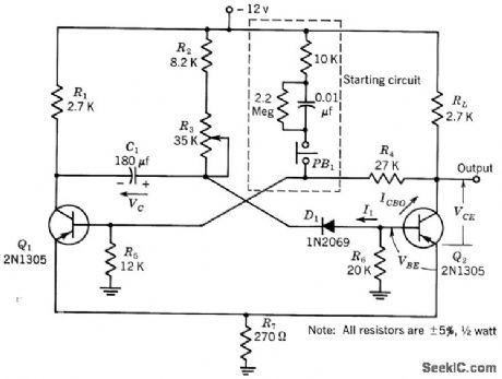
Designed to switch 4-mct load having 12.v supply. Output is -12 v for period that can be adjusted from. 1 to 5 sec. Timing is accurate within 10 from -20 to +60℃.-Texas Instruments Inc., Transistor Circuit Design, McGrctw4iill, N.Y., 1963, p 413. (View)
View full Circuit Diagram | Comments | Reading(630)
REPEAT_CYCLE_TIMER
Published:2009/7/23 22:12:00 Author:Jessie
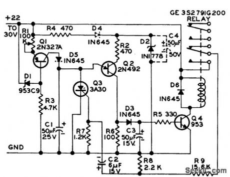
Provides output pulses over dynamic range of several thousand. Will tolerate large ripple from power source. If D4, D5, and C4 are added as shown in darted lines, will tolerate transients up to 100% of supply voltage with several microsec duration.-Low-Frequency Stairstep Generator and Timing Circuit, Electronic Circuit Design Handbook, Mactier Pub. Corp., N.Y., 1965, p 144. (View)
View full Circuit Diagram | Comments | Reading(1021)
SATURABLE_REACTOR_TIMER
Published:2009/7/23 22:11:00 Author:Jessie
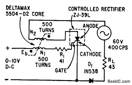
Varying d-c bias voltage applied to control winding or saturable reactor changes time for magnetic flux to reach final value, permitting use of circuit us frequency divider for timing applications. In 400-cps circuit shown, division can be adjusted over range front 1 to 10. Output diode prevents thermal runaway in controlled rectifier when anode is going negative and gate is positive to cathode.-J. S. Sicko, Counting and Timing Circuits Use Saturable Reactor, Electronics, 33:19, p 61-63. (View)
View full Circuit Diagram | Comments | Reading(1066)
Pulse_generator
Published:2009/7/23 22:57:00 Author:Jessie

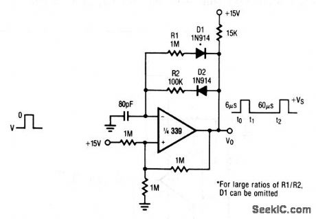
This circuit uses only one section of a 339 comparator and produces pulses of 6-μs duration with 60-μs spacing, using the values shown. Raytheon Linear Integrated Circuts, 1989, p. 5-31. (View)
View full Circuit Diagram | Comments | Reading(0)
HYBRID_GERMANIUM_BOXCAR
Published:2009/7/23 22:18:00 Author:Jessie
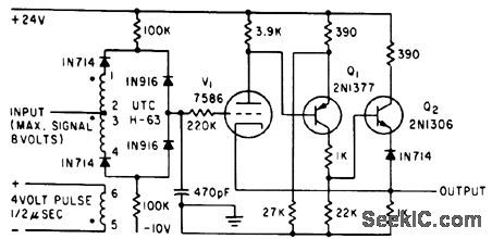
Provides time selection and storage of waveforms, as required for radar mti, sensing elements of tracking radars, and gated agc. Power drain is negligible except for 7586 nuvistor filament power of about 1 W.-A. G. Lloyd, Half-Bridge Inverter Provides Economical Three-Phase Power, Electronics, 34:37, p 62-65. (View)
View full Circuit Diagram | Comments | Reading(486)
BASIC_THYRATRON_TIMER
Published:2009/7/23 22:16:00 Author:Jessie

Is not completely linear, partly because of contact potential in grid circuit, but nonlinearity errors are usually less than 3% up to about 60 sec.-R. L. Ives, Timer Made More Linear, Electronics, 32:5, p 66-69. (View)
View full Circuit Diagram | Comments | Reading(848)
SONAR_BEARING_INDICATOR
Published:2009/7/23 22:18:00 Author:Jessie
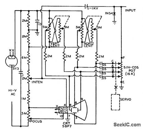
Visual indicator using ordinary cro can be synchronized with rotating directional underwater acoustic transducer, to indicate relative bearing of arriving signal from target. Transducer synchro output, proportional to bearing, drives small servo motor having standard 4-fop sine-cosine potentiometer. Detector output is applied across pot, and four vector outputs are fed to cathode-ray deflection plates. A-c voltage produces rotating bar, and diode clipping of half the signal converts bar to pointer emanating from center of screen. With target signal present, input amplitude is adjusted to produce line from center to edge of screen.-Target Bearing Indicator, Electronic Circuit Design Handbook, Mactier Pub. Corp., N.Y., 1965, p 123. (View)
View full Circuit Diagram | Comments | Reading(631)
Complete_three_chip_AM_radio_station
Published:2009/7/23 22:18:00 Author:Jessie

This circuit is a complete microphone-to-an tenna AM radio station, producing a stable 1-Vpp 1-MHz signal at the antenna. Construction and operation of this circuit might require FCC review and/or licensing. The carrier is generated by A1, connected as a quartz-stabilized oscillator, similar to that of Fig. 5-18. The A1 output is applied to modulated RF power-output stage A2. Microphone amplifier A3 supplies bias to pins 1 and 8 of A2, resulting in an amplitude-modulated RF carrier at the A2 output. The circuit is calibrated by adjusting the 50-Ω oscillator potentiometer for a stable 1-Vpp 1-MHz signal at the A1 output. (View)
View full Circuit Diagram | Comments | Reading(603)
HYBRID_SILICON_BOXCAR
Published:2009/7/23 22:18:00 Author:Jessie
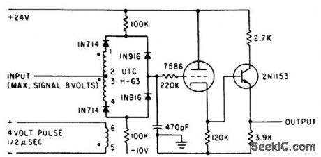
Signal-to-noise ratio of silicon hybrid is up to 2 db better than germanium at all temperatures. Only one transistor is needed for high-temperature stability. Input to boxcar should be from 150-ohm source.-A. G. Lloyd, Half-Bridge Inverter Provides Economical Three-Phase Power, Electronics, 34:37, p 62-65. (View)
View full Circuit Diagram | Comments | Reading(467)
UNDERSEA_PROPAGATION_TRANSMITTER
Published:2009/7/23 22:17:00 Author:Jessie
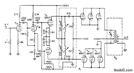
Develops 100-v peak signal across 100-ohm matched resistive load of crystal transducer, for mean power output of 50 w. Is fed by r-f oscillator through transmitter gate that generates voltage pulse whose width is variable from 10 to 5,000 microsec, to turn on transmitter for corresponding time. P1 and P2 are plug-in circuits that must be changed when operating frequency is changed in range of 25 to 150 kc.-W. C. Gore, Ultrasonics Tests Undersea Propagation, Electronics, 31 :35, p 32-35. (View)
View full Circuit Diagram | Comments | Reading(519)
SAMPLE_AND_HOLD
Published:2009/7/23 22:17:00 Author:Jessie

Uses bilateral charging to increase energy content of series of low-duty-cycle amplitude-modulated pulses resulting from demultiplexing one channel of porn pulse train. Designed for sampling and holding 0 to 5 V information received via sampled-data telemetry link.-Sample and Hold Circuit with Bilateral Charging, Electronic Circuit Design Handbook, Mactier Pub. Corp., N.Y., 1965, p 131. (View)
View full Circuit Diagram | Comments | Reading(0)
Nokia 6110 circuit diagram 03
Published:2011/8/1 22:13:00 Author:Ecco | Keyword: Nokia 6110

View full Circuit Diagram | Comments | Reading(1163)
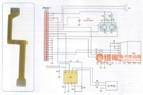
Konka 7388 cell phone cable schematic circuit diagram
Published:2011/8/1 22:31:00 Author:Ecco | Keyword: Konka 7388, cell phone cable
View full Circuit Diagram | Comments | Reading(1029)
Nokia 6110 circuit diagram 04
Published:2011/8/1 22:27:00 Author:Ecco | Keyword: Nokia 6110

View full Circuit Diagram | Comments | Reading(518)
Nokia 6310 circuit diagram 05
Published:2011/8/1 22:28:00 Author:Ecco | Keyword: Nokia 6310

View full Circuit Diagram | Comments | Reading(565)
| Pages:52/126 At 204142434445464748495051525354555657585960Under 20 |
Circuit Categories
power supply circuit
Amplifier Circuit
Basic Circuit
LED and Light Circuit
Sensor Circuit
Signal Processing
Electrical Equipment Circuit
Control Circuit
Remote Control Circuit
A/D-D/A Converter Circuit
Audio Circuit
Measuring and Test Circuit
Communication Circuit
Computer-Related Circuit
555 Circuit
Automotive Circuit
Repairing Circuit