
Index 45
POLICE_SIREN_USES_FLASHER
Published:2009/7/22 1:07:00 Author:Jessie

Low-drain circuit operating from 1.5-V cell uses National LM3909 flasher ICs to simulate whooper sounds of electronic sirens used on some city police cars and ambulances. Two flashers are required for generating required rapidly rising and falling modulating voltage. Transistor is connected as diode to force ramp generator of IC to have longer ON periods than OFF periods, raising average tone and making modulation seem more even.-P. Lefferts, Power-Miser Flasher IC Has Many Novel Applications, EDN Magazine, March 20, 1976, p 59-66. (View)
View full Circuit Diagram | Comments | Reading(746)
TRIODE_CLAMP_MODULATOR
Published:2009/7/22 1:02:00 Author:Jessie
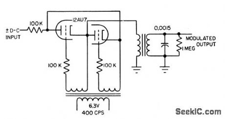
Dual-triode performs chopper function. With 6.3 v rms carrier, output is linear to 2 v rms for d-c inputs up to 25 v. Null level is 100 my, but can be reduced by filtering. Long-time drift stability is excellent. Output signal is nor molly square-wave, but tuned circuit shown converts this to sinusoidal signal.-L. S.Klivans, Modulators for Automatic Control Systems, Electronics, 31:1, p 82-84. (View)
View full Circuit Diagram | Comments | Reading(673)
Electronically_programmed_timer_using_an_Intersil_8240_50_60_16_pin_DIP
Published:2009/7/22 0:09:00 Author:Jessie
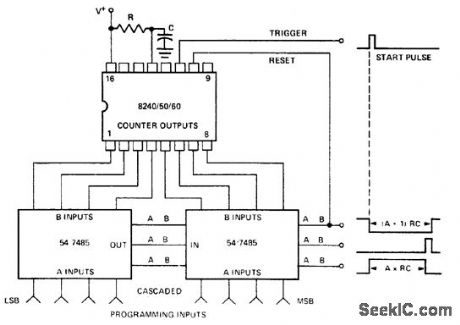
Electronically programmed timer using an Intersil 8240/50/60 16-pin DIP. This circuit uses a standard 54/74 series TTL 4-bit magnitude comparator to compare the digitally programmed input with the 8240/50/60 counter outputs. The greater, less-than and equal waveforms provide several outputs to choose from. An external start pulse triggers the timer and the A<B output is used as a reset (courtesy Intersil, Inc.). (View)
View full Circuit Diagram | Comments | Reading(1611)
Electronically_programmed_counter_using_the_Intersil_8240_50_60_16_pin_DIP
Published:2009/7/22 0:05:00 Author:Jessie
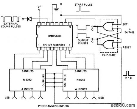
Electronically programmed counter using the Intersil 8240/50/60 16-pin DIP. Two quad exclusive-NOR circuits with open-collector outputs are wired together to form an inexpensive digital comparator. A start pulse triggers the 8240/50/60 counter and sets the output flip-flop high. The digital comparator output goes high momentarily when A is equal to B. This resets the flip-flop, which in turn resets the counter. For extended temperature range or higher speed operation individual pull-up resistor may be required on the counter outputs (courtesy Intersil, Inc.). (View)
View full Circuit Diagram | Comments | Reading(1318)
800_W_soft_start_light_dimmer
Published:2009/7/22 3:35:00 Author:Jessie

This circuit shows the basic UJT building block (Fig. 9-1), which is used in a light dimmer with soft-start operation that applies current to the light slowly enough to eliminate high surges (high inrush current). These current surges, found in most cold-filament light dimmers, shorten lamp life. With this circuit, the lamp is heated slowly by a gradually increasing voltage so that inrush current is kept to a minimum. R4 controls the charging rate of C2 and provides the means to control or dim the lamp. (View)
View full Circuit Diagram | Comments | Reading(0)
R_C_COUPLED_BASE_MODULATION
Published:2009/7/22 1:17:00 Author:Jessie

Modulation signal is injected by using two resistors, volues of which are determined by available r-f drive power; higher power is needed for larger resistance values. Excellent linearization of waveform is obtained with Re from 10 to 30 ohms. Rb should be in range from 100 to 2,000 ohms, with 470 as good com promise value. Modulation of 100% is easily achieved for CB transmitter.-B. Rheinfelder, Modulation Techniques for Transistorized A-M Transmitters, EEE, 11:7, p 54-57. (View)
View full Circuit Diagram | Comments | Reading(663)
DUO_DIODE_HALF_WAVE_SWITCH_MODULA_TOR
Published:2009/7/22 1:14:00 Author:Jessie

Tube serves in place of chopper. Carrier voltage turns diodes on and off, transferring d-c input signal to output when diodes are not conducting. With 10-v rms carrier voltage, output is linear up to 2 v for inputs up to 5 v d-c.-L. S. Klivans, Modulators for Automatic Control Systems, Electronics, 31:1, p 82-84. (View)
View full Circuit Diagram | Comments | Reading(725)
10_V_SIREN_CHIP
Published:2009/7/22 1:14:00 Author:Jessie

One section of National MM74C908/MM74C918 dual CMOS driver is used as audio VCO and other section as voltage ramp generator that varies frequency of VCO. Combination gives siren effect at low cost, with output current up to 250mA for driving loudspeaker.- CMOS Databook, National Semiconductor, Santa Clara, CA, 1977, p 5-38-5-49. (View)
View full Circuit Diagram | Comments | Reading(736)
Half_wave_thyristor_control_with_average_voltage_feedback
Published:2009/7/22 1:54:00 Author:Jessie

This circuit shows a UJT used as a thyristor trigger (with feedback), where the average load voltage is the desired feedback variable. R1, R2, and C1 average the load voltage so that the voltage can be compared with the set point that is determined by RC. (View)
View full Circuit Diagram | Comments | Reading(721)
High_speed_FIFO_memory_using_the_MC10143_register_file
Published:2009/7/22 2:24:00 Author:Jessie


High-speed FIFO memory using the MC10143 register file (courtesy Motorola Semiconductor Products Inc.). (View)
View full Circuit Diagram | Comments | Reading(758)
Shift_right_shift_left_register_with_parallel_inputs
Published:2009/7/22 3:32:00 Author:Jessie
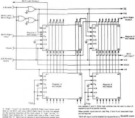
Shift-right/shift-left register with parallel inputs (courtesy Motorola Semiconductor Products Inc.). (View)
View full Circuit Diagram | Comments | Reading(1168)
High_wattage_lamp_control
Published:2009/7/22 3:21:00 Author:Jessie
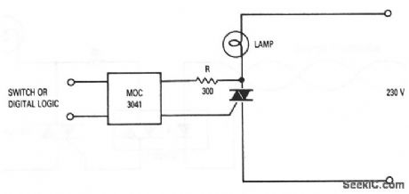
Many high-wattage incandescent lamps suffer shortened lifetimes when switched on at ac line voltages other than zero. This is because a large inrush of current destroys the filament. A simple solution to this problem is to use an optoisolator and triac, as shown. The triac must be capable of handling the lamp current. The MOC3041 optoisolator can be controlled from a switch or some form of 5-V digital logic. The minimum value of R is determined by the maximum surge current rating of the MOC3041 (ITSM), where: Rmin(pk) /ITSE; With a 230-V line, and a 1.2-A ITSM for the MOC3041, the minimum value of R is: 340 V/1.2A =283 Ω. (View)
View full Circuit Diagram | Comments | Reading(1172)
CMOS_256_word_by_n_bit_static_read_write_memory
Published:2009/7/22 3:19:00 Author:Jessie
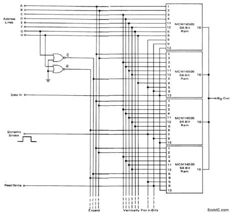
CMOS 256-word by n-bit static read/write memory (courtesy Motorola Semiconductor Products Inc.). (View)
View full Circuit Diagram | Comments | Reading(641)
Multiple_line_driver_buffer
Published:2009/7/23 21:11:00 Author:Jessie
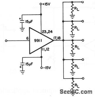
This circuit shows a 9911 used as a driver for multiple lines, which allows a video signal to be routed to 5 (or more) individual directions. A typical application is an apartment building with a common cable system. Although the 9911 is capable of 500-mA drive at a± 10-V output voltage swing, this application usually does not require more than± 1 or±2 V (for a typical video system). This circuit can be inexpensive because only one voltage-follower/buffer and few external components are needed. (View)
View full Circuit Diagram | Comments | Reading(620)
Optoisolator_driver_for_resistive_loads
Published:2009/7/22 6:02:00 Author:Jessie
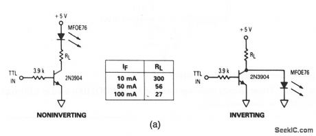

These circuits show a visible red LED (MFOE76) that is used as fiberoptic drivers for both noninverting and inverting TTL inputs. Figure 9-34B shows typical fiberoptic termination and assembly for both receivers and transmitterS. (View)
View full Circuit Diagram | Comments | Reading(910)
4_decade_synchronous_counter_with_data_display_multiplexing
Published:2009/7/22 4:17:00 Author:Jessie
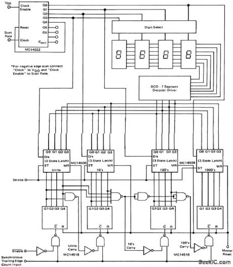
4-decade synchronous counter with data display multiplexing (courtesy Motorola Semiconductor Products Inc.). (View)
View full Circuit Diagram | Comments | Reading(707)
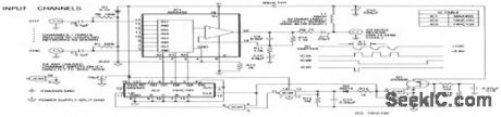
SPEECH_NETWORK
Published:2009/7/6 20:49:00 Author:May

The XR-T5995 Speech Network is a monolithic integrated circuit specifically designed for implementing a low cost telephone circuit. It is designed to use an electrodynamic microphone and electromagnetic receiver to replace a carbon microphone and telephone network hybrid.
(View)
View full Circuit Diagram | Comments | Reading(6015)
Manual_automatic_PROM_programmer
Published:2009/7/22 3:49:00 Author:Jessie
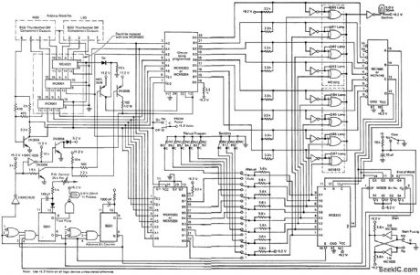
Manual/automatic PROM programmer (courtesy Motorola Semiconductor Products Inc.). (View)
View full Circuit Diagram | Comments | Reading(666)
ELECTRO_EXPLOSIVE_DEVICE_TESTER
Published:2009/7/23 1:32:00 Author:Jessie
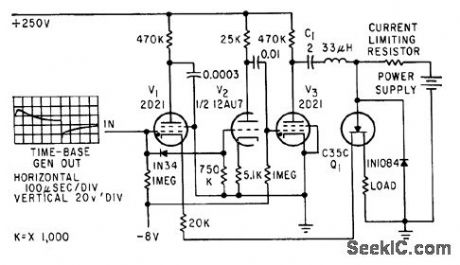
Uses combination of tubes and solid-stctte thyrairon to generate single pulse up to 100 ump with duration of several millisec, for testing detonators, primers, squibs, and explosive switches.-V. W. Goldie, R. G. Amicone, and C. T. Davey, Generating Pulses With Solid. State Thyratrons, Electronics, 32;33, p 70. (View)
View full Circuit Diagram | Comments | Reading(792)
Video_system_remote_multiplexer_box
Published:2009/7/22 22:37:00 Author:Jessie

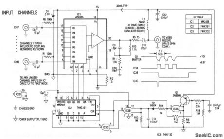
The heart of the remote multiplexer box in the single-coax video system (Fig. 3-14) is a combination 8-channel multiplexer and amplifier (IC1). C11couples the MUX baseband video output to the coax, and L1 decouples the video from dc power arriving on the same line. This power (about 30 mA at 10 V) supplies all circuitry in the multiplexer box. Channel-select signals generated at the interface box (11 pulse for channel 0, 8 pulses for channel7) pulse the 10-V supply to 8.8 V and back at a 10-Hz rate. Q1 and associated components in the remote multiplexor box convert these pulses to 5-V logic levels, which block the 4-bit counter IC2. In turn, IC2 selects the desired multiplexor channel. The first pulse of a burst selects channel 0. Subsequent pulses, arriving before the discharge of timeout network R13/C 13 advance IC2 by one count each. Thus, channel 0 appears almost instantly, and channel 1, when selected, appears near the end of a 0.8-s burst. (View)
View full Circuit Diagram | Comments | Reading(2943)
| Pages:45/126 At 204142434445464748495051525354555657585960Under 20 |
Circuit Categories
power supply circuit
Amplifier Circuit
Basic Circuit
LED and Light Circuit
Sensor Circuit
Signal Processing
Electrical Equipment Circuit
Control Circuit
Remote Control Circuit
A/D-D/A Converter Circuit
Audio Circuit
Measuring and Test Circuit
Communication Circuit
Computer-Related Circuit
555 Circuit
Automotive Circuit
Repairing Circuit