
Index 43
Programmable_100_hour_timer_with_display
Published:2009/7/21 23:00:00 Author:Jessie

Programmable 100-hour timer with display. The 8260 on the right uses the carryout gate to generate a t -second clock from the 60-hertz line. The diodes on the time base input rectify the input signal and alternately clamp and release the internal pull-up resistor at pin 14. The input network depends on the amplitude of the 60-hertz signal available. The internal oscillators are disabled with a t K resistor at pin 13. The second and third 8260s are programmable with thumbwheel switches up to 59 seconds and 59 minutes. The carryout of each divider drives the next counter. The 8250 was chosen to give the maximum count of 99 hours. All request pins are tied together and back to the 10K output pull-up resistors at the thumbwheels. The timing cycle begins by pressing the pushbutton. The 7045 provides a counter chip pulse direct drive to the 7-segment LEDs. Timing resolution can be increased to hundredths of a second by substituting 8250s for the initial stages and using the 60-hertz line to generate a 100-hertz clock (courtesy Intersil, Inc.). (View)
View full Circuit Diagram | Comments | Reading(1602)
Improved_lamp_dimmer
Published:2009/7/21 22:59:00 Author:Jessie

This circuit is an improved version of the circuit shown in Fig. 8-21. The hysteresis effect is eliminated by the addition of two diodes and the 5.1 -kΩ resistor. The RC network across the triac is a snubber to prevent line transients from accidentally firing the triac. The circuit operates from a 120-V 60-Hz source, and can control up to 1000 W of power to incandescent bulbs (but not fluorescents). (View)
View full Circuit Diagram | Comments | Reading(1930)
Low_cost_lamp_dimmer
Published:2009/7/21 22:56:00 Author:Jessie
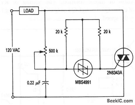
This circuit shows a full-range, low-cost, lamp dimmer that uses an MBS4991 silicon bilateral switch (SBS) to trigger the triac. The two 20-kΩ shunt resistors minimize the flash-on or hysteresis effect of the SBS, and improve the temperature sensitivity. (View)
View full Circuit Diagram | Comments | Reading(0)
Ring_counter_that_transfers_power_sequentially_to_a_series_of_n_loads
Published:2009/7/21 22:56:00 Author:Jessie

Ring counter that transfers power sequentially to a series of n loads (courtesy Motorola Semiconductor Products Inc.). (View)
View full Circuit Diagram | Comments | Reading(940)
Direction_and_speed_control_for_shunt_wound_motors
Published:2009/7/21 22:54:00 Author:Jessie

This circuit is similar to that of Fig. 8-19, except that the shunt field is placed across the rectified supply and the motor armature is placed in the SCR bridge. Thus, the field current is always in the same direction, but the armature current is reversible, so the direction of rotation is reversible (as determined by which transformer, T1 or T2, is selected through the switch). Again, motor speed is set by R1. (View)
View full Circuit Diagram | Comments | Reading(0)
PLL_clock_for_an_ADC1100_BIN_dual_slope_A_D_convener
Published:2009/7/21 22:52:00 Author:Jessie

PLL clock for an ADC1100/BIN dual-slope A/D convener (courtesy Analog Devices, Inc.). (View)
View full Circuit Diagram | Comments | Reading(533)
Direction_and_speed_control_for_series_wound_or_universal_motors
Published:2009/7/21 22:51:00 Author:Jessie

In this circuit, Q1 through Q4 are triggered in diagonal pairs. The pair to be turned on is controlled by S1, which selects either T1 or T2 to receive a pulse from Q5. Current in the motor field is reversed by selecting either Q2 and Q3, or Q1 and Q4, for conduction. Because motor armature current is always in the same direction, the field current reverses in relation to the armature current, which thus reverses the direction of motor rotation. The setting of R1 determines the conduction angle of either Q1 through Q4 or Q2/Q3, thus setting the average motor voltage and thereby the speed. (View)
View full Circuit Diagram | Comments | Reading(632)
Alternate_motor_speed_control_with_tachometer_feedback
Published:2009/7/21 22:48:00 Author:Jessie

This circuit is an alternate to that shown in Fig. 8-17, but with a lower parts count. The same magnet-coil tachometer shown in Figs. 8-17B and 8-17C can be used with the circuit of Fig. 8-18. Motor speed is controlled by the 100-kΩ pot. (View)
View full Circuit Diagram | Comments | Reading(965)
Sequential_UJT_SCR_timer_circuit
Published:2009/7/21 22:45:00 Author:Jessie

Sequential UJT-SCR timer circuit. This circuit is useful in washing machine circuits where different time cycles are required (courtesy Motorola Products Inc.). (View)
View full Circuit Diagram | Comments | Reading(1748)
CLASSIC_OP_AMP_ASTABLE_MULTIVIBRATOR
Published:2009/7/7 1:00:00 Author:May

Uses CA3130 BiMOS op amp that operates at a frequency of 1 kHz. With rail-to-rail output swing, frequency is independent of supply voltage, device, and temperature. 0nly the temperature coefficient of RT and CT enters into circuit stability. (View)
View full Circuit Diagram | Comments | Reading(1207)
Motor_speed_control_with_tachometer_feedback
Published:2009/7/21 22:44:00 Author:Jessie

This circuit shows a triac motor-speed control that derives feedback from a magnet-coil tachometer that is placed near the motor fan (Figs. 8-17B and 8-17C). Motor speed is controlled by the 5-kΩ pot. The MAC210-4 triac is capable of handling motor loads up to 10 A. (View)
View full Circuit Diagram | Comments | Reading(3015)
Time_delay_circuit_using_a_UJT
Published:2009/7/21 22:40:00 Author:Jessie

Time delay circuit using a UJT. Maximum time delay is set by the 10M pot. Time delay can be set from less than a second to approximately 2.5 minutes (courtesy Motorola Semiconductor Products Inc.). (View)
View full Circuit Diagram | Comments | Reading(1203)
20_METER__DIRECT_CONVERSION
Published:2009/7/21 22:37:00 Author:Jessie

Well-designed circuit provides pleasing polarity and depth of sound, with SSB signals seeming to stand out against nearly noiseless background. Covers entire 20-meter band. Use of balanced-product detector improves stability to reject strong broadcast-band AM signals. BFO energy from Q4 is injected through center tap of broad-band toroidal transformer L4-L5. Except for preselector, selectivity is obtained only through shaping of audio channel. Bandwidth is more appropriate for CW if C7 is increased to 0.02 or 0.047μF. T1 is 10K to 2K CT Stancor TAPC-35.L2 is 40 turns No. 30 enamel on T-37.6 core, with 2 turns No. 28 on it for L1 and 4 turns for L3. L5 is 16turns No. 28 on FT-37-63 core, with center tap, with 4turns No.28 on it for L4, L6is 19turns No. 28 on 7-37-6 core, tapped 7 turns above ground.-J. Rusgrove, A 20-Meter High-Performance Direct-Conversion Receiver, OST, April 1978, p 11-13. (View)
View full Circuit Diagram | Comments | Reading(3102)
Fluorescent_starter
Published:2009/7/21 22:36:00 Author:Jessie

This circuit shows a solid-state fluorescent-lamp starter that uses a SIDAC. In this circuit, the ballast is identical to that used with a conventional glow-tube starter. (View)
View full Circuit Diagram | Comments | Reading(2586)
Xeon_flasher
Published:2009/7/21 22:34:00 Author:Jessie

This circuit shows an xeon tube triggered by a SIDAC that is connected as a basic relaxation oscillator, where the frequency is determined primarily by the RC time constant (a SIDAC relaxation oscillator is shown in Fig. 5-40). Once the capacitor voltage reaches the SIDAC breakover voltage (as determined by the setting of the series potentiometer), the SIDAC fires, and dumps the charged capacitor. By placing the load (transformer-coupled xeon tube) in the discharge path, the flashing frequency can be controlled. (View)
View full Circuit Diagram | Comments | Reading(2006)
TRANSISTOR_CURVE_TRACER_1
Published:2009/7/21 22:33:00 Author:Jessie

Staircase wave-form generator supplies lest transistor with six values of base current during etch cycle, to develop family of curves for cro. Range switches give wide choice of test voltages and currents. Four-layer and tunnel diodes can also be checked.-C. J. Candy, Simplified Curve Tracer for Transistors and Diodes, Electronics, 33:34, p 68-70. (View)
View full Circuit Diagram | Comments | Reading(3909)
10_MHz_universal_counter_using_the_Intersil_ICM7216B_28_pin_DIP
Published:2009/7/21 23:14:00 Author:Jessie

10 MHz universal counter using the Intersil ICM7216B 28-pin DIP. This circuit can use input frequencies up to 10MHz at input A and up to 2 MHz at input B (courtesy Intersil, Inc.). (View)
View full Circuit Diagram | Comments | Reading(1322)
SCR_control_circuit_with_dc_output_that_uses_an_SBS
Published:2009/7/21 23:10:00 Author:Jessie

This circuit is similar to that of Fig. 8-25, except that a provided to the load. With MCR3818-4 controlled rectifiers mounted heatsink, this circuit will control up to 3-kW power froma 120-V line. (View)
View full Circuit Diagram | Comments | Reading(812)
Ultralong_delay_timer_using_two_8240_16_pin_DIPs
Published:2009/7/21 23:07:00 Author:Jessie

Ultralong delay timer using two 8240 16-pin DIPs. The time base of unit 2 is disabled. The output is normally high when the system is reset. Upon application of a trigger the output goes low and stays that way for a duration of (256)2 or 65,536 cycles of the time base oscillator. Total timing cycle of the circuit is programmed from To = 256RC to To = 65,536RC in 256 discrete steps by selecting any combination of the counter outputs of unit2 (courtesy Intersil, Inc.). (View)
View full Circuit Diagram | Comments | Reading(618)
Basic_SCR_control_circuit_that_uses_an_SBS
Published:2009/7/21 23:07:00 Author:Jessie

This figure shows the basic control circuit for SCRs that use SBS triggers, and is preferable to that of Fig. 8-24 (triac), where high power must be handled, or whore rapidly rising voltages are encountered (high dv/dt,). Although the circuits of both Figs. 8-24 and 8-25 were designed as incandescent-lamp dimmers, the circuits are well suited to control of universal and shaded-pole motors. Such motors have higher torque at low speeds when open-loop controlled by these circuits, rather than with rheostats or variable transformers (because of the higher voltage pulses applied). (View)
View full Circuit Diagram | Comments | Reading(796)
| Pages:43/126 At 204142434445464748495051525354555657585960Under 20 |
Circuit Categories
power supply circuit
Amplifier Circuit
Basic Circuit
LED and Light Circuit
Sensor Circuit
Signal Processing
Electrical Equipment Circuit
Control Circuit
Remote Control Circuit
A/D-D/A Converter Circuit
Audio Circuit
Measuring and Test Circuit
Communication Circuit
Computer-Related Circuit
555 Circuit
Automotive Circuit
Repairing Circuit