
Index 46
TELEPHONE_HOLD_BUTTON
Published:2009/7/6 20:39:00 Author:May


The on-hook (no load) voltage across the red-green wires will be 48 V or slightly less when all telephones are on-hook (disconnected). When any telephone goes off-hook the load current flowing in the telephone causes the voltage to fall below 5 volts dc.Although the telephone hold is connected across the red-green wires, silico1i control rectifier SCR1 is open; so there is no current path across the telephone line. To hold the call, depress normally-open switch S1 and hang up the telephone (still depressing S1). When the phone goes on-hook the red-green voltage jumps to 48 volts dc. Since switch S1 is closed, a positive voltage is applied to SCR1's gate, which causes SCR1 to conduct, thereby completing the circuit across the telephone line through D1, LED1, R1, and SCR1. The current that flows through those components also causes the LED to light up-indicating that the telephone line is being held. The effective load across the red-green wires is the 1500 ohm value of R1, which is sufflcient to seize the line while limiting the current through the LED to a safe value. When the telephone, or an extension, is once again placed off-hook the red-green voltage falls to 5 volts or less.But diode D1 has a normal voltage drop-called the breakover voltage-of 0.7 volts, and the LED has a forward drop of 2.0 volts. Excluding the voltage drop across R1 there is a maximum of 2.3 volts available for SCR1, which is too low to maintain conduction; so SCR1 automatically opens the hold circuit when any telephone goes off-hook. (View)
View full Circuit Diagram | Comments | Reading(95)
Video_power_and_channel_select_on_a_single_coax
Published:2009/7/22 22:34:00 Author:Jessie

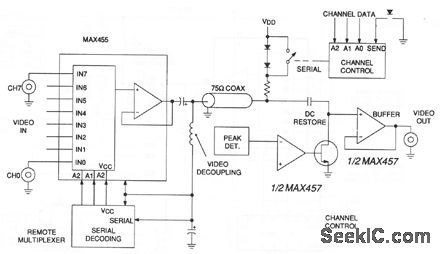
In this video system, a single coaxial cable carries power to the remote location, selects one of eight video channels, and returns the selected signal. The system can choose one of several remote surveillance-camera signals, for example, and display the picture on a monitor near the channel-select box. Circuit details are shown in Figs. 3-15 and 3-16. (View)
View full Circuit Diagram | Comments | Reading(556)
PLUG_IN_REMOTE_TELEPHONE_RINGER
Published:2009/7/6 20:37:00 Author:May

This device consists of a ring detector connected to the telephone line. When the telephone rings, the ring detector impresses high-frequency pulses on the ac power line.A receiver placed anywhere on the same power line detects these pulses and emits an audible tone in synchronization with the telephone signal. (View)
View full Circuit Diagram | Comments | Reading(998)
Stabilized_wideband_cable_driving_amplifier_with_low_input_capacitance
Published:2009/7/22 22:32:00 Author:Jessie
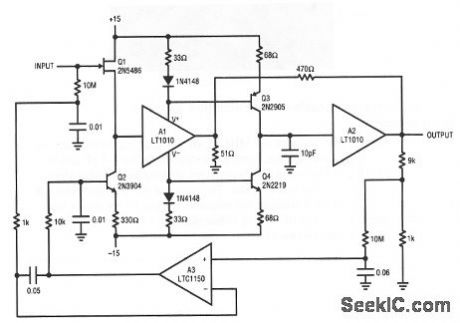
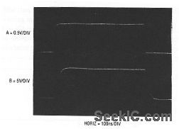
This circuit has over 20 MHz of small-signal bandwidth driving 100-mA loads, capacitance or cable. Input capacitance is below 1.5 pF and bias current is about 100 pA. The output is fully protected, making the amplifier ideal as a video A/D input buffer or as a cable driver. The amplifier also permits wideband probing when scope probe loading is not tolerable. Figure 3-13B shows large-signal performance at a gain of 10, driving 10 feet of cable. A fast input pulse (trace A) produces the output shown (trace B). (View)
View full Circuit Diagram | Comments | Reading(624)
HIGH_ISOLATION_TELEPHONE_RINGER
Published:2009/7/6 20:33:00 Author:May

The diode rectifies the ringing signal to supply the operating power to the audio relaxation oscillator made up of L1, L2, R1, R2, and C. Moreover, L2 together with Q1 acts as an opto-isolator, totally isolating the telephone line from the rest of the circuit.The oscillator audio frequency is optically coupled to the photo-Darlington which drives Q2 and thus the speaker. The 10 μF capacitor is not large enough to smooth the ringing ripple completely. This results in frequency modulation of the audio oscillator giving it an attention-getting warble.
(View)
View full Circuit Diagram | Comments | Reading(637)
PHONE_LIGHT
Published:2009/7/6 20:32:00 Author:May

When the phone does ring the triac is triggered into conduction by a signal applied to its gate (G) through a bilateral switch (diac), D2. The triac acts as a switch, conducting only when a signal is present at the gate.
(View)
View full Circuit Diagram | Comments | Reading(745)
CIRCUIT_MONITORS_BLINKING_PHONE_LIGHTS
Published:2009/7/6 20:31:00 Author:May

A 2N5777 photo-Darlington cell picks up blinking light from the transparent plastic buttons. The power is switched ON and OFF by a hibeta 2N3904 transistor. The circuit's 9 V battery can be left continuously connected. Less than a microampere is drawneven with normal, office ambient light and the phone lights not flashing. For noisy locations, the tone can be made louder with an output transformer (ratio of 250:8) or a 100 ohm speaker that replaces the 22 ohm resistor in the output. (View)
View full Circuit Diagram | Comments | Reading(1577)
TELEPHONE_RINGING_DETECTORFREQUENCY_AND_VOLUME_CONTROLLED
Published:2009/7/6 20:28:00 Author:May

With the 555 timer connected as a multivibrator and an opto-isolator, a remote speaker can be driven. (View)
View full Circuit Diagram | Comments | Reading(695)
AUTOMATIC_TELEPHONE_RECORDING_DEVICE
Published:2009/7/6 20:27:00 Author:May

The device is a dc switch that is normally on via the forward biasing of Q1 via R3.Q1 now clamps Q2 into a forward state by biasing its complement well into a saturated state via R4. The dc switch is turned off via a negative voltage above that of the zener (D1). This voltage is usually about 48 and is the on-hook value of the phone line. This negative voltage overrides the effect of R3 and keeps the circuit off. When the phone is off the hook, the 48 vblts drops to 10 volts, that is below the zener voltage of D1 and R3 now tums the circuit on. The audio signal is via attenuator resistor R1 and dc isolating capacitors C1, C2. The device is a high impedance switch that isolates the recording controlled device from the phone line via some relatively simple electronic circuitry. It requires no battery and obtains power for operating via the remote jack that in most recorders is a source of 6 volts. When clamped to ground it initiates recorder operation. The unit interfaces with most portable cassette recorders providing they contain a remote control jack.
(View)
View full Circuit Diagram | Comments | Reading(737)
DUAL_TONE_DECODING
Published:2009/7/6 20:26:00 Author:May

Two integrated tone decoders, XR-567 units, can be connected (as shown in Fig.1A) to permit decoding of simultaneous or sequential tones. Both units must be on before an output is given. RIC1 and R'1C'1 are chosen, respectively, for Tones 1 and 2. If sequential tones (1 followed by 2) are to be decoded, then C3 is made very large to delay turn-off of Unit Luntil Unit 2 has turned on and the NOR gate is activated. Note that the wrong sequence (2 followed by 1) will not provide an output since Unit 2 will turn off before Unit 1 comes on. Figure 1B shows a circuit variation which eliminates the NOR gate. The output is taken from Unit 2, but the Unit 2 output stage is biased off by R2 and CR1 until activated by Tone 1. A further variation js given in Fig. IC.Here, Unit 2 is turned on by the Unit 1 output wh.en Tone 1 appears, reducing the standby power to half. Thus, when Unit 2 is on, Tone 1 is or was present. If Tone 2 is now present, Unit 2 comes on also and an output is given. Since a transient output pulse may appear at Unit 1 turn-on, even if Tone 2 is not present, the load must be slow in response to avoid a false output due to Tone 1 alone. The XR-267 Dual Tone Decoder can replace two integrated tone decoders in this application.
(View)
View full Circuit Diagram | Comments | Reading(678)
Low_frequency_divider
Published:2009/7/22 4:05:00 Author:Jessie
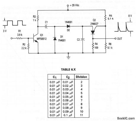
This circuit shows a PUT that is used as a frequency divider, where the ratio of C1 and C2 determines the amount of division. For a 10-kHz input frequency, and an amplitude of 3 V, Table 6-X shows the values for C1 and C2 that are needed to divide by values from 2 to 11. The division range can be changed by changing the ratio R6/(R6 + R5). With a given C1 and C2, increasing the resistance ratio increases the division range. (View)
View full Circuit Diagram | Comments | Reading(0)
Low_voltage_lamp_flasher_that_uses_a_PUT
Published:2009/7/22 3:59:00 Author:Jessie
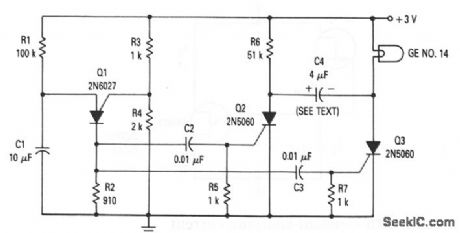
This circuit shows a PUT used as a lamp flasher, where the supply is only 3 V. Q1, R1, and C1 form a relaxation oscillator. Q2 and Q3 form an SCR flip-flop. Notice that C4 is not a polarized capacitor. For the values shown, the lamp is on and off for about 0.5 s each. (View)
View full Circuit Diagram | Comments | Reading(1000)
TTL_Photodetector_fiberoptic_receiver
Published:2009/7/22 4:30:00 Author:Jessie
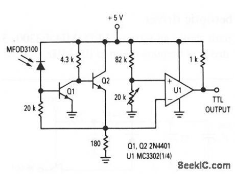
This circuit shows a photo detector (MFOD3100) that is used as a fiberoptic receiver with a TTL output, operating at frequencies up to 1 MHz. (View)
View full Circuit Diagram | Comments | Reading(873)
TTL_infrared_LED_fiberoptic_driver
Published:2009/7/22 4:28:00 Author:Jessie
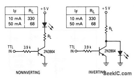
These circuits show an infrared LED (MFOE3200, 3201, 3202) that is used as fiberoptic drivers for both noninverting and inverting TTL inputs. (View)
View full Circuit Diagram | Comments | Reading(1676)
100_MHz_frequency_and_2_MHz_ρeriod_counter_using_an_Intersil_ICM7216A_28_pin_DIP
Published:2009/7/22 4:27:00 Author:Jessie
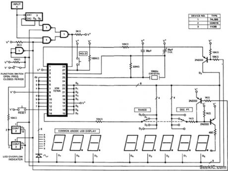
100 MHz frequency and 2 MHz ρeriod counter using an Intersil ICM7216A 28-pin DIP (counesy Intersil, Inc.). (View)
View full Circuit Diagram | Comments | Reading(812)
Infrared_LED_fiberoptic_driver
Published:2009/7/22 4:23:00 Author:Jessie
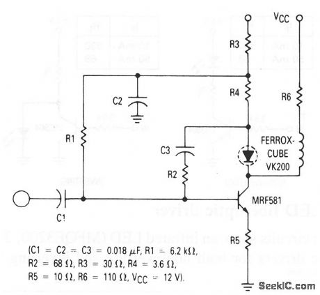
This circuit shows an infrared LED (MFOE3200, 3201, 3202) that is used as a fiberoptic driver at frequencies up to 100 MHz. (View)
View full Circuit Diagram | Comments | Reading(609)
Optocoupler_driven_SCR
Published:2009/7/22 21:48:00 Author:Jessie
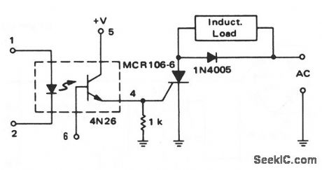
This circuit shows a 4N26 driving an SCR, which, in turn, is used to control an inductive load. The SCR is a sensitive-gate device ( 1 mA of gate current) and the 4N26 has a minimum-current transfer ratio of 0.2, so the 4N26 input current (IF) must be 5 mA. The 1-kΩ resistor prevents the SCR from triggering with small input changes, and the 1N4005 prevents the SCR from triggering with the self-induced voltage when the SCR turns off. (View)
View full Circuit Diagram | Comments | Reading(2925)
Video_amplifier_dc_stabilization_summing_point_technique
Published:2009/7/22 7:57:00 Author:Jessie
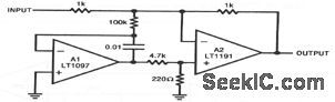
In this circuit, A2 handles high-frequency inputs while A1 stabilizes the dc operating point. The 4.7 k-220-Ω divider at the A2 input prevents excessive drive during start-up. The circuit combines the A135-μV offset and 1.5 V/℃ drift with the A2450 V/μs slew rate and 90-MHz bandwidth. Bias current, dominated by A2, is about 500 nA. (View)
View full Circuit Diagram | Comments | Reading(521)
Loop_through_video_cable_receiver
Published:2009/7/22 7:53:00 Author:Jessie
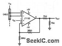
In this circuit, an LT1193 differential amplifier is placed across a distribution cable to extract the video signal. Common-mode signals are rejected by the LT1193 differential inputs. Differential gain and phase errors measure 0.02% and 0.1°, respectively. A separate input permits dc level adjustment. (View)
View full Circuit Diagram | Comments | Reading(549)
Wideband_log_IF_strip
Published:2009/7/22 6:48:00 Author:Jessie


The SL1615 shown in this figure is a bipolar wideband amplifier for use in successive-detection log IF strips. (View)
View full Circuit Diagram | Comments | Reading(620)
| Pages:46/126 At 204142434445464748495051525354555657585960Under 20 |
Circuit Categories
power supply circuit
Amplifier Circuit
Basic Circuit
LED and Light Circuit
Sensor Circuit
Signal Processing
Electrical Equipment Circuit
Control Circuit
Remote Control Circuit
A/D-D/A Converter Circuit
Audio Circuit
Measuring and Test Circuit
Communication Circuit
Computer-Related Circuit
555 Circuit
Automotive Circuit
Repairing Circuit