Electrical Equipment Circuit
LOW_FREQUENCY_DIVIDER
Published:2009/7/1 1:41:00 Author:May | From:SeekIC


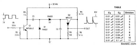
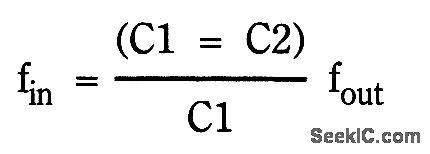
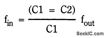
The ratio of capacitors C1 and C2 determines division. With a positive pulse applied to the base of Q1, assume that C1 = C2 and that C1 and C2 are discharged. When Q1 turns off, both C1 and C2 charge to 10 volts each through R3. On the next pulse to the base of Q1, C1 is again discharged but C2 remains charged to 10 volts. As Q1 turns off this time, C1 and C2 again charge. This time C2 charges to the peak point firing voltage of the PUT causing it to fire. This discharges capacitor C2 and allows capacitor C1 to charge to the line voltage. As soon as C2 discharges and C1 charges, the PUT turns off. The next cycle begins with another positive pulse on the base of Q1 which again discharges C1. The input and output frequency can be approximated by the equationFor a 10 kHz input frequency with an amplitude of 3 volts, the table shows the values for C1 and C2 needed to divide by 2 to 11.
Reprinted Url Of This Article:
http://www.seekic.com/circuit_diagram/Electrical_Equipment_Circuit/Low_frequency_divider.html
Print this Page | Comments | Reading(3)

Article Categories
power supply circuit
Amplifier Circuit
Basic Circuit
LED and Light Circuit
Sensor Circuit
Signal Processing
Electrical Equipment Circuit
Control Circuit
Remote Control Circuit
A/D-D/A Converter Circuit
Audio Circuit
Measuring and Test Circuit
Communication Circuit
Computer-Related Circuit
555 Circuit
Automotive Circuit
Repairing Circuit
Code: