
Index 42
ROAD_ICING_ALARM
Published:2009/7/21 20:54:00 Author:Jessie

Sensing transmitter mounted on auto about 2 feel above rood, with junction of transistor connected to case is connected to low-frequency oscillator having lamp load. R7 is adjusted so lamp is out but on verge of flashing of 2℃. When temperature drops, lamp flashes. Duration of each lash increases down to 0℃ after which lamp remains on.-J. A. Irvine, Reducing Winter Skids with a Transistor Warning Circuit, Electronics, 36:4, p 56-58. (View)
View full Circuit Diagram | Comments | Reading(622)
Manual_512_bit_PROM_programmer
Published:2009/7/21 20:53:00 Author:Jessie

Manual 512-bit PROM programmer (courtesy Motorola Semiconductor Products Inc.). (View)
View full Circuit Diagram | Comments | Reading(664)
100_MODULAIION_OF_LIGHT_EMITTING_DIODE
Published:2009/7/22 1:10:00 Author:Jessie

Inpt of 0.35 v rms at 1 kc gives 100% modulation. Useful operating range of circuit is 30 cps to 25 kc for light-beam communication.-E. t. Bonin, Drivers for Optical Diodes, Electronics, 37:22, p 77-82. (View)
View full Circuit Diagram | Comments | Reading(536)
Basic_triac_zero_point_switch
Published:2009/7/21 23:16:00 Author:Jessie

This circuit shows a manually controlled zero-point switch that is useful in power control for resistive loads. Q2 turns on near zero on both the positive and negative half-cycles of the line input. When S1 is closed, Q1 turns on, shunts gate current away from Q2, and keeps Q2 from turning on during either half cycle. The 2N6346 triac shown will handle resistive loads up to 8 A. (View)
View full Circuit Diagram | Comments | Reading(915)
Long_life_circuit_for_an_incandescent_lamp
Published:2009/7/21 22:26:00 Author:Jessie

This circuit shows an MKP9V270 SIDAC used to phase-control anincandescent lamp,thus lowering the RMS voltage to the filament and prolongingthe life ofthe bulb,This is particularly useful when lamps are used In hard to reachlocations,such as In outdoor lighting In stgns where replacement costs are high. Bulb life span can be extended by 1.5 to 5 times,depending on the type of lamp,theamount of power reduction to the filament,and the number of times the lamp is switched on from a cold filament condition. Practical conduction angles runbetween 110°and 130°,with corresponding power reductions of 10%to 30%. (View)
View full Circuit Diagram | Comments | Reading(1002)
FET_ADAPTER_FOR_CURVE_TRACER
Published:2009/7/21 21:59:00 Author:Jessie

Used to convert input current steps from Tektronix 575 or other curve tracer lo output voltage steps for let gate.-R. Williams, Adapter for Curve Tracer Tests FET's at High Voltage, Electronics, 39:5, p 104-105. (View)
View full Circuit Diagram | Comments | Reading(1845)
Digitally_controlled_time_delay
Published:2009/7/21 21:42:00 Author:Jessie

Digitally controlled time delay. This circuit generates a time delay controlled by the digital input of the AD7520. The current fed into the integrator's summing point at OUT 1 is determined by the D/A converter's input. The output of the integrator remains low until the trigger input of the 555tmergoes low. At that time the timer's output goes high, unclamping the output and permitting the integrator to change upward until it reaches 2/3VDD, at which time the timer's output goes low and the integrator is reset to zero. The time delay is D/D1REF×10V, where D is the fractional binary equivalent of the digital input word (courtesy Analog Devices, Inc.). (View)
View full Circuit Diagram | Comments | Reading(645)
THERMISTORS_CORRECT_THRMETEAR_LINEARITY
Published:2009/7/21 21:40:00 Author:Jessie
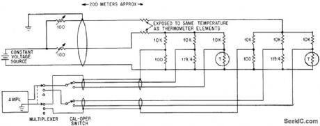
Zero-temperature-coefficient resistors mounted near resistance thermometer element offset variation of lead resistance with temperature.-F. J. Goldwater, Low-Cost Digital System Records Weather Data, Electronics, 37;2, P 34-36. (View)
View full Circuit Diagram | Comments | Reading(515)
Simple_dc_power_control
Published:2009/7/21 21:37:00 Author:Jessie

This circuit shows a simple dc full-wave control scheme that uses an SCR and an SBS. Control is obtained by varing the 100-kΩ pot. Notice that R1, can be omitted when triacs with nonsensitive gates are used. (View)
View full Circuit Diagram | Comments | Reading(928)
Full_range_ac_power_control
Published:2009/7/21 21:47:00 Author:Jessie

This circuit shows a full-range ac control scheme that uses a triac and SBS. Control is obtained by varying the 100-k Ω pot. Notice thatRGK can be omitted when nonsensitive gates are used. The double time constants of this circuit produce low hysteresis, which thus extends the control range. (View)
View full Circuit Diagram | Comments | Reading(687)
20_minute_long_duration_timer_using_a_PUT
Published:2009/7/21 21:47:00 Author:Jessie

20-minute long-duration timer using a PUT (courtesy Motorola Semiconductor Products Inc.). (View)
View full Circuit Diagram | Comments | Reading(693)
SPIKE_CLIPPER
Published:2009/7/21 22:16:00 Author:Jessie

Improves efficiency of low-power SSB amateur transmitter by removing from voice waveform the spikes that cause over modulation or give low average modulation level. When used as in-line microphone amplifier, circuit gives up to 20-dB equivalent gain at receiving location.-H. E. Weber, Increase Your SSB Efficiency, 73 Magazine, Dee. 1973, p 71. (View)
View full Circuit Diagram | Comments | Reading(752)
Zero_crossing_switch_for_sensitive_gate_SCRs
Published:2009/7/21 22:15:00 Author:Jessie

This circuit is primarily for sensitive-gate SCRs, such as the 2N4216, and loads of 1.5 A or less. (View)
View full Circuit Diagram | Comments | Reading(588)
PARAMP_TEST_SET
Published:2009/7/21 22:14:00 Author:Jessie

Supplies c-w signal that can be injected into parametric amplifier under test, and indicates relative power output of paramp on meter. Test set also has 30-Mc output for feeding automatic noise-figure meter.-C. F. Brett, Parometric Amplifier for Space Probe Tracking, Electronics, 34:4, p 41-45.
(View)
View full Circuit Diagram | Comments | Reading(1113)
Ultralong_delay_timer_using_two_8250_16_pin_DIPs
Published:2009/7/21 22:14:00 Author:Jessie

Ultralong delay timer using two 8250 16-pin DIPs. The output is normally high when reset, and goes low upon application of a trigger input. It stays low for a duration of (100)2 or 10,000 cycles. Total timing cycle for the two 8250s can be programmed from TO = 1RC to TO = 9999RC in 10,000 discrete steps by selectively shorting any combination of pins 1 through 8 from both units to the output bus (courtesy Intersil, Inc.). (View)
View full Circuit Diagram | Comments | Reading(579)
TUNNEL_DIODE_TEST_ATTACHMENT_FOR_CURVE_TRACER
Published:2009/7/21 22:12:00 Author:Jessie

Adapter switches sweep voltages of curve tracer on and off at re duced duty cycle to prevent overheating of tunnel diode while determining its series resistance. Increasing R1 gives lower duty cycle, because R1-R2 control frequency of inductively coupled series-resonance feed-back oscillator Q1.-L. M. Zappulla, Low Duty Cycle Tunnel-Diode Tester, Electronics, 35:4, p 47. (View)
View full Circuit Diagram | Comments | Reading(1653)
TUNNEL_DIODE_SWITCHING_TIME_TESTER
Published:2009/7/21 22:08:00 Author:Jessie

With values shown, will light only if tunnel diode under test switches within 0.5.nsec.-J. E. Gersbach and I. Lieber, Switching-Time Tester for Tunnel Diodes, Electronics, 35:16, p 48-49. (View)
View full Circuit Diagram | Comments | Reading(698)
SSB_CW_DEMODULATOR
Published:2009/7/21 22:26:00 Author:Jessie

LM373 communication IC uses balanced mixer as product detector, with reinserted carrier reapplied to pin 6. CW or SSB output is taken from pin 7. If desired, RF gain control can be inserted in AGC feedback path.-E. M. Noll, Linear IC Principles, Experiments, and Projects, Howard W. Sams, Indianapolis, IN, 1974, p 350-351. (View)
View full Circuit Diagram | Comments | Reading(2565)
Zero_crossing_switch_with_SCR_slave_configuration
Published:2009/7/21 22:22:00 Author:Jessie

This circuit provides a single pulse to the gate of SCR Q2 each time that SCR Q1 turns on, thus turning Q2 on for the half-cycle following the half-cycle during which Q1was on. Q2 is turned on only when Q1 is turned on, and the load can be controlled by a signal applied to the gate of Q1. The control signal can be either dc or a power pulse. The SCR used must be capable of handling the maximum current requirements of the load to be driven. The 8-A 200-V SCRs shown will handle a 1-kW load. 2N6397s can also be used in this circuit, and will hands up to 12 A. (View)
View full Circuit Diagram | Comments | Reading(745)
Zero_crossing_switch_for_nonsensitive_gate_SCRs
Published:2009/7/21 22:19:00 Author:Jessie

This circuit is primarily for nonsensitive-gate SCRs, such as the 2N4442 (or an MCR218-8), and loads of 8.0 A or less. (View)
View full Circuit Diagram | Comments | Reading(749)
| Pages:42/126 At 204142434445464748495051525354555657585960Under 20 |
Circuit Categories
power supply circuit
Amplifier Circuit
Basic Circuit
LED and Light Circuit
Sensor Circuit
Signal Processing
Electrical Equipment Circuit
Control Circuit
Remote Control Circuit
A/D-D/A Converter Circuit
Audio Circuit
Measuring and Test Circuit
Communication Circuit
Computer-Related Circuit
555 Circuit
Automotive Circuit
Repairing Circuit