
Index 51
DC Voltage Meter Wiring Method Circuit
Published:2011/8/2 8:55:00 Author:Robert | Keyword: DC, Voltage, Meter, Wiring, Method

The picture shows the DC voltage meter wiring method circuit.
The voltage meter is used to measure the voltage of electrical line voltage. When measuring it could connect the voltage meter directly to the circuit, which is shown in the picture. When wiring it should be noted that the positive and negative polar of the voltage meter and the wire's positive and negative polar should be corresponding. It the voltage meter measurement mechanism's internal resistor R is not large enough, and also the measurement voltage is a little higher, in this case it should add a serial resistor R to reduce the meter mechanism's voltage. The resistor in this circuit is also called voltage doubler. (View)
View full Circuit Diagram | Comments | Reading(531)
TDA2003 Reference Material Circuit
Published:2011/7/30 9:02:00 Author:Robert | Keyword: Reference, Material

The features of TDA2003:The TDA2003's current output capacity is strong and also it has low harmonic distortion and crossover distortion. Its every pin has the AC and DC short circuit protection and it could be used safely. The voltage on the load could get 40V.The TDA2003's pin function and pin definition.The maximum rated value Tamb=25.Parameter name, symbol, ultimate value, unit.power peak voltage (50ms), Vccp, 40, V.DC power voltage, Vcc, 28, V.Working power voltage, Vcc, 18, V.Output repetitive peak voltage, Io, 3.5, A.Output not repetitive peak voltage, Io, 4.5, A.Power consumption T=90, PD, 20, W.Storage temperature, Tstg, -40, +150, degree.Welding temperature, Tj, -40, +150, degree. (View)
View full Circuit Diagram | Comments | Reading(635)
LM317 Current Expanding Circuit 3
Published:2011/8/1 11:02:00 Author:Robert | Keyword: Current, Expanding

The picture shows the LM317 current expanding circuit 3.
This picture is the parallel current expanding circuit's principle circuit. It is made up of two adjustable voltage regulators LM317. The input port's voltage V1=25V and the output current Io=Io1+Io2=3A. The output voltage's adjustable range is 1.2V to 22V. In this LM317 current expanding circuit, the integrated operational amplifier 741 is used to balance the two voltage regulator's output current. If the LM317-1's output current Io1 is larger than the LM317-2's output current Io2, the voltage drop on resistor R1 would increase, the operational amplifier's in-phase voltage Vp (=V1-I1R1) would decrease and the operational amplifier's output port's voltage Vao would decrease. By the adjusting port adj1 it would make the output Vo decrease and make the output current Io1 decrease so that it would be balanced. Otherwise it would be the same principle. By adjusting the resistor R5 it would adjust the output voltage's value. (View)
View full Circuit Diagram | Comments | Reading(3808)
Korean RE-630D Mechanical Microwave Oven Circuit
Published:2011/8/2 3:13:00 Author:Robert | Keyword: Korean, Mechanical, Microwave, Oven

The picture shows the Korean RE-630D mechanical microwave oven circuit.
The circuit in the picture is in open mode.
The ST is temperature control device. The S1 is door first interlock switch. The S2 is door second interlock switch. The S3 is door monitoring switch. The EL is oven lamp. The M1 is timing motor. The M2 is rotating plate motor. The M3 is fan motor. The T is high-voltage transformer. The C is high-voltage capacitor. The V is high-voltage diode. The MT is magnetron. The S4 is timer switch. The S5 is power selection switch. (View)
View full Circuit Diagram | Comments | Reading(2826)
UPPERCASE_DRIVE_FOR_TV_GRAPHICS
Published:2009/7/5 22:25:00 Author:May

Alphameric data-to-video converter using 2513 character generator accepts ASCII words from microprocessor memory and three line commands from instruction decoder. Five dots are outputted simultaneously, corresponding to one row on 5 x 7 dot-matrix character. 7416S eight-input one-output shift register converts dots into serial output video. Input repeats to generate all seven dot rows in row of characters. Shift register is driven by high-frequency timing circuit that delivers LOAD pulse once each microsecond along with CLOCK output running continuously at desired dot rate. Optional cursor uses 4584 5-Hz oscillator for cursor winking rate. If ASCII input bit 8 is high, cursor input goes high and output is white line on leads 01 through 05. Right diode mades this line blink, while Ieft diode allows winking cursors only during valid character times.-D. Lancaster, TVT Hardware Design. Kilobaud, Jan. 1978, p 64-68. (View)
View full Circuit Diagram | Comments | Reading(1521)
REFERENCE_FREQUENCY_SAMPLER
Published:2009/7/23 22:07:00 Author:Jessie
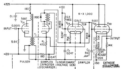
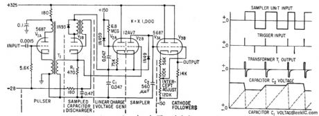
Improves discrimination of f-m signals from magnetic tape, with fastest possible response to wide-deviation frequency-modulated transients. Constant reference frequency is recorded on one tape channel. When playback output voltage is made proportional to quotient of data and reference frequencies, output is independent of tape speed, and wow and flutter components are cancelled. Reference discriminator shown provides voltage output proportional to period of preceding cycle. -P. S. Bengston, Sampling Discriminators for Data Reduction, Electronics, 32:13, p 70-72. (View)
View full Circuit Diagram | Comments | Reading(600)
DIODE_TESTER_2
Published:2009/7/23 22:07:00 Author:Jessie
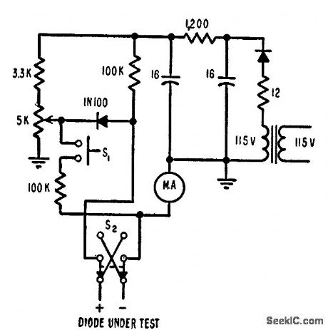
Measures germanium diode reverse (leakage) current rapidly at 50 v back voltage, with no shock hazard and no danger to meter or diode even if diode is shorted or inserted incorrectly. S1 converts meter from ammeter to voltmeter for measuring test terminal voltage. R2 adjusts test voltage to desired half-scale meter reading value. S2 permits checking diode in both directions.-I. J. Levy, Reverse-Current Tester Speeds Diode Checks, Electronics, 31:1, p 88-90. (View)
View full Circuit Diagram | Comments | Reading(787)
Time-Varying Dimming Circuit
Published:2011/7/29 8:47:00 Author:Robert | Keyword: Time, Varying, Dimming
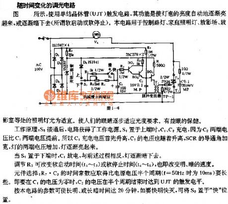
The picture shows the time-varying dimming circuit.As shown, it uses the unijunction transistor (UJT) trigger circuit, whose function is that it could make the lamp's brightness light up gradually and automatically, or light out gradually and automatically (which means the so-called soft starting or soft stopping). This circuit could be used to control street lamp, home lamp, film-playing place, film-playing room and so on, and these cases would be very adequate. This could make people's eyes adapt to the photometric requirements gradually, so that it is good for eye's health.The working principle: when the S3 is connected, the circuit would get power supply. If the S1 is switched to upside, the C1, C2 would be charged. Because the C2's two ports' voltage is advanced than the C1's two ports' voltage, the C1's charging voltage would be increased firstly and the C2 voltage would follow it to be increased. The SCR's conduction angle would be wider and the lamp's two ports' voltage would be increased, so the lamp would be light up gradually. (View)
View full Circuit Diagram | Comments | Reading(573)
Infrared Remote-Control Receiver Head Substitution Method Circuit
Published:2011/7/29 18:23:00 Author:Robert | Keyword: Infrared, Remote-Control, Receiver Head, Substitution, Method
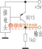
The picture shows the infrared remote-control receiver head substitution method circuit.
The infrared receiver head, which is used in the household appliances with remote-control function, has a big range of models. So when repairing it usually meets the case of unable buying the original model of receiver head. And it could only to find a substitution product. In practice it could use the common models for substitution of whatever types of the receiver heads. When it needs substitution it should be noted that:1.Mounting dimensions.If the original model of receiver head has a large size then it would select expediently any size-equivalent models for substitution and also it can use a smaller size model for substitution. Currently there is a micro-receiver head which looks like a plastic-package triode. It could be used for repairing substitution conveniently. (View)
View full Circuit Diagram | Comments | Reading(563)
NV-M8000 Camera Box-Out Control Working Principle Circuit And Common Troubleshooting Circuit
Published:2011/7/29 19:03:00 Author:Robert | Keyword: Camera, Box-Out, Control, Working Principle, Common, Troubleshooting
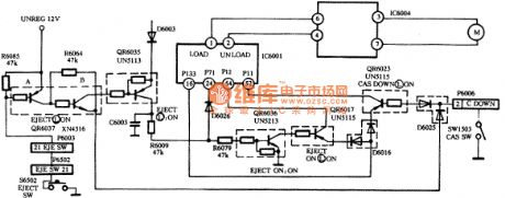
The NV-M8000 camera box-out control circuit is made up of system control microprocessor IC6001 and transistors QR6037, QR6035, QR6036, QR6017, QR6023 and EJECT button switch S6520 and cassette holder down switch SW1503 and so on, which is shown in the picture.
The working principle.
When it is in cassette holder down mode, the cassette holder down switch SW1503 would be connected under the function of the cassette holder lockplate control lever. The QR6023's base polar would connect the plug-in module D6006's pin 2 through K6025, and then through the cassette holder down switch it gets to the ground. QR6023's base polar is conducted in low voltage level. IC6001's pin 16 (CSANOUT) signal would connect the its pin 52 (CSANIN) through QR6023. The microprocessor would be in stopping mode when it receives the cassette holder down signal. (View)
View full Circuit Diagram | Comments | Reading(638)
Panasonic M3500 Camera Power Supply Working Principle Circuit And Troubleshooting Circuit
Published:2011/7/29 19:29:00 Author:Robert | Keyword: Panasonic, Camera, Power Supply, Working Principle, Troubleshooting
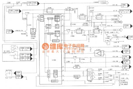
The Panasonic M-series Cameras are popular in the counties and television enterprises, schools, audio-visual halls, individual wedding camera crews and some families, and the society has a large amount of these products. This series has many advantages such as full functions, easy to use, good video quality, video tapes can be played directed by the VHS camera and so on. Currently these cameras have entered the maintenance period. So the author take the Panasonic NV-M3500 type camera as example to introduce this type of devices' circuit principle and troubleshooting method. In the circuit, those types which is similar to this types such as NV-M3000, NV-M9000, NV-M9500, NV-DP200 and other types and the Panasonic M series old types such as NV-M7, NV-M1000, NV-M8000 and other cameras, could also take reference from the method introduced in this article for maintenance. (View)
View full Circuit Diagram | Comments | Reading(1836)
DIAL_TELEPHONE_TESTER
Published:2009/7/23 21:59:00 Author:Jessie
Delivers large pulses without being sensitive to changes in load, through use of thyratron in flip-flop.- thyratron Used for Bistable Circuit, Electronics, 32:6, p 64-65. (View)
View full Circuit Diagram | Comments | Reading(591)
High_performance_mtxer
Published:2009/7/23 21:59:00 Author:Jessie
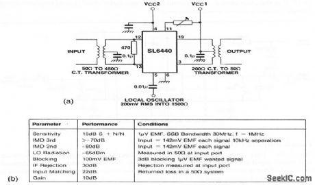
This circuit shows an SL6440 (Fig. 2-10) mixer with transformer coupling. Figure 2-20B shows the circuit characteristics. (View)
View full Circuit Diagram | Comments | Reading(1095)
Break_before_make_delay
Published:2009/7/23 21:58:00 Author:Jessie
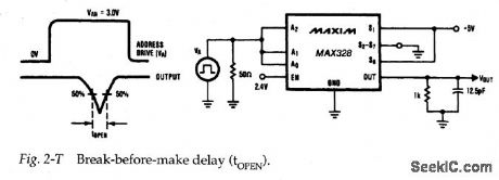
Figure 2-T shows a test circuit for measuring break-before-make delay for the MAX328/29, Again, a pulse is required at the analog inputs. Typical break-before-make delay is 0.2 μps. (View)
View full Circuit Diagram | Comments | Reading(759)
FET_TIMER
Published:2009/7/23 22:15:00 Author:Jessie
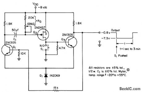
Darlington-like pair Q2-Q3 serve with Q1 as monostable mvbr, most useful as timer because high input impedance allows use of modest capacitors to obtain long time delays. In stable state, Q2 is on and Q3 is saturated, holding Q1 off.-L. J. Sevin, Jr. Field-Effect Transistors, McGraw-Hill, N.Y., 1965, p 89. (View)
View full Circuit Diagram | Comments | Reading(680)
Input_protected_differential_input_data__acquisition_system_
Published:2009/7/23 22:10:00 Author:Jessie
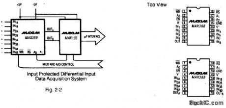
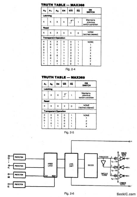


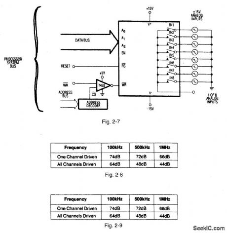
Figures 2-2 and 2-3 show a typical application circuit and pin configurations, respectively, for the MAX368/69,Figures 2-4 and 2-5 show the logic truth tables, respectively, for the MAX368 and MAX369.As shown In Fig,2-6、these fault-protected analog mux ICs have a latch function SO that both write WR and reset RS signals are required. Figure -7 shows the IC connected with a bus interface.Figure 2-8 shows the typical off- isolation rejection ratio. Figure 2-9 shows typical crosstalk-rejection ratio. MAXIM NEW RELEASES DATA Book, 1992,P. 1-31、1-37,1-40,1-44,1-46,1-47. (View)
View full Circuit Diagram | Comments | Reading(558)
MEASURING_VALVE_CLOSING_TIME
Published:2009/7/23 22:10:00 Author:Jessie
Determines exact time of valve closure from wave-shape of current in solenoid. Energizing cur rent is differentiated and shaped, to trigger circuits that measure interval between solenoid switch closing and final solenoid osition.-R. L. Kissner, Determining Closure Time in Missile Control Vales, Electronics, 33:42, p 88-89. (View)
View full Circuit Diagram | Comments | Reading(583)
COLD_CATHODE_SAMPLING_COUNTER
Published:2009/7/23 22:06:00 Author:Jessie
Transistor-blocking oscillator drives cold-cathode counter tube to give long-life decade counter having low power consumption. Used in automatic recorder for data from several hundred radioactive samples per day. Maximum repetition rate is 200 pps.-H. Sadowski and M. E. Cassidy, How Transistor Drives Cold-Cathode Counter, Electronics, 32:38, p 46-47. (View)
View full Circuit Diagram | Comments | Reading(577)
Charge_injection_tests
Published:2009/7/23 22:05:00 Author:Jessie
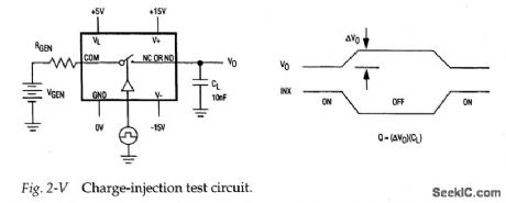
Figure 2-V shows a test circuit for measuring charge injection for the MAX301/ 3/5. Notice that charge injection (Q) is measured in coulombs (C). A pulse is applied to the control pin and the difference in output voltage is noted. Q is calculated when the difference in output voltage is divided by the capacitance at the output. Typical charge injection is 10 to 15pC. (View)
View full Circuit Diagram | Comments | Reading(708)
PULSE_COUNT_SAMPLE_TIME_RECORDER
Published:2009/7/23 22:04:00 Author:Jessie
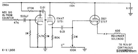
Amplifier and thyratron trigger feed pulse to solenoid pen of recorder, to record time of end of counting period, corresponding to instant at which counter delivers negative pulse.-C. F. Miller, New Phototransistor Tachometers Measure Missile Spin, Electronics, 35:25, p 33-35. (View)
View full Circuit Diagram | Comments | Reading(617)
| Pages:51/126 At 204142434445464748495051525354555657585960Under 20 |
Circuit Categories
power supply circuit
Amplifier Circuit
Basic Circuit
LED and Light Circuit
Sensor Circuit
Signal Processing
Electrical Equipment Circuit
Control Circuit
Remote Control Circuit
A/D-D/A Converter Circuit
Audio Circuit
Measuring and Test Circuit
Communication Circuit
Computer-Related Circuit
555 Circuit
Automotive Circuit
Repairing Circuit