Electrical Equipment Circuit
Input_protected_differential_input_data__acquisition_system_
Published:2009/7/23 22:10:00 Author:Jessie | From:SeekIC
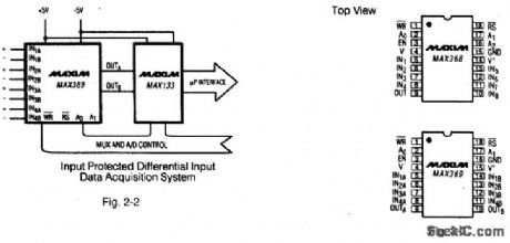
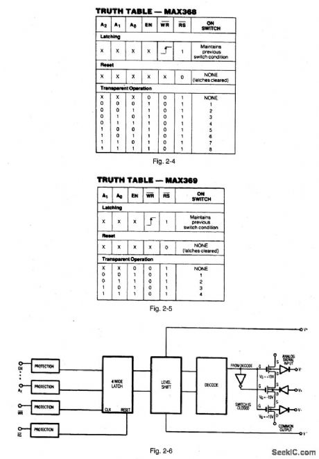
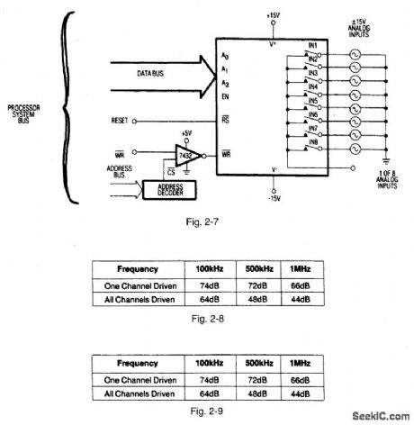


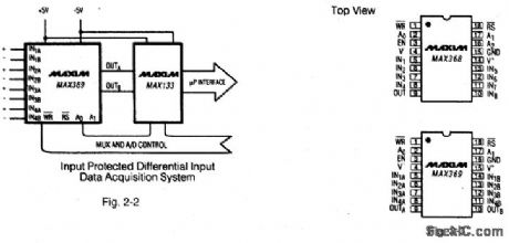

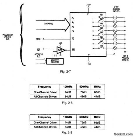
Figures 2-2 and 2-3 show a typical application circuit and pin configurations, respectively, for the MAX368/69,Figures 2-4 and 2-5 show the logic truth tables, respectively, for the MAX368 and MAX369.As shown In Fig,2-6、these fault-protected analog mux ICs have a latch function SO that both write WR and reset RS signals are required. Figure -7 shows the IC connected with a bus interface.Figure 2-8 shows the typical off- isolation rejection ratio. Figure 2-9 shows typical crosstalk-rejection ratio. MAXIM NEW RELEASES DATA Book, 1992,P. 1-31、1-37,1-40,1-44,1-46,1-47.
Reprinted Url Of This Article:
http://www.seekic.com/circuit_diagram/Electrical_Equipment_Circuit/Input_protected_differential_input_data__acquisition_system_.html
Print this Page | Comments | Reading(3)

Article Categories
power supply circuit
Amplifier Circuit
Basic Circuit
LED and Light Circuit
Sensor Circuit
Signal Processing
Electrical Equipment Circuit
Control Circuit
Remote Control Circuit
A/D-D/A Converter Circuit
Audio Circuit
Measuring and Test Circuit
Communication Circuit
Computer-Related Circuit
555 Circuit
Automotive Circuit
Repairing Circuit
Code: