Electrical Equipment Circuit
Direction_and_speed_control_for_series_wound_or_universal_motors
Published:2009/7/21 22:51:00 Author:Jessie | From:SeekIC
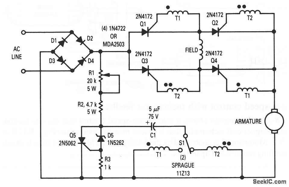
In this circuit, Q1 through Q4 are triggered in diagonal pairs. The pair to be turned on is controlled by S1, which selects either T1 or T2 to receive a pulse from Q5. Current in the motor field is reversed by selecting either Q2 and Q3, or Q1 and Q4, for conduction. Because motor armature current is always in the same direction, the field current reverses in relation to the armature current, which thus reverses the direction of motor rotation. The setting of R1 determines the conduction angle of either Q1 through Q4 or Q2/Q3, thus setting the average motor voltage and thereby the speed.
Reprinted Url Of This Article:
http://www.seekic.com/circuit_diagram/Electrical_Equipment_Circuit/Direction_and_speed_control_for_series_wound_or_universal_motors.html
Print this Page | Comments | Reading(3)

Article Categories
power supply circuit
Amplifier Circuit
Basic Circuit
LED and Light Circuit
Sensor Circuit
Signal Processing
Electrical Equipment Circuit
Control Circuit
Remote Control Circuit
A/D-D/A Converter Circuit
Audio Circuit
Measuring and Test Circuit
Communication Circuit
Computer-Related Circuit
555 Circuit
Automotive Circuit
Repairing Circuit
Code: