Electrical Equipment Circuit
Video_system_remote_multiplexer_box
Published:2009/7/22 22:37:00 Author:Jessie | From:SeekIC


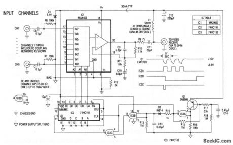
The heart of the remote multiplexer box in the single-coax video system (Fig. 3-14) is a combination 8-channel multiplexer and amplifier (IC1). C11couples the MUX baseband video output to the coax, and L1 decouples the video from dc power arriving on the same line. This power (about 30 mA at 10 V) supplies all circuitry in the multiplexer box. Channel-select signals generated at the interface box (11 pulse for channel 0, 8 pulses for channel7) pulse the 10-V supply to 8.8 V and back at a 10-Hz rate. Q1 and associated components in the remote multiplexor box convert these pulses to 5-V logic levels, which block the 4-bit counter IC2. In turn, IC2 selects the desired multiplexor channel. The first pulse of a burst selects channel 0. Subsequent pulses, arriving before the discharge of timeout network R13/C 13 advance IC2 by one count each. Thus, channel 0 appears almost instantly, and channel 1, when selected, appears near the end of a 0.8-s burst.
Reprinted Url Of This Article:
http://www.seekic.com/circuit_diagram/Electrical_Equipment_Circuit/Video_system_remote_multiplexer_box.html
Print this Page | Comments | Reading(3)

Article Categories
power supply circuit
Amplifier Circuit
Basic Circuit
LED and Light Circuit
Sensor Circuit
Signal Processing
Electrical Equipment Circuit
Control Circuit
Remote Control Circuit
A/D-D/A Converter Circuit
Audio Circuit
Measuring and Test Circuit
Communication Circuit
Computer-Related Circuit
555 Circuit
Automotive Circuit
Repairing Circuit
Code: