Electrical Equipment Circuit
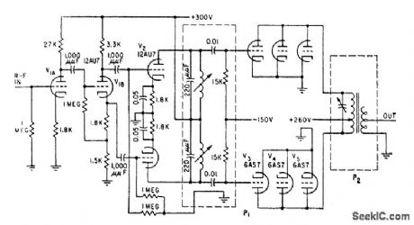
UNDERSEA_PROPAGATION_TRANSMITTER
Published:2009/7/23 22:17:00 Author:Jessie | From:SeekIC

Develops 100-v peak signal across 100-ohm matched resistive load of crystal transducer, for mean power output of 50 w. Is fed by r-f oscillator through transmitter gate that generates voltage pulse whose width is variable from 10 to 5,000 microsec, to turn on transmitter for corresponding time. P1 and P2 are plug-in circuits that must be changed when operating frequency is changed in range of 25 to 150 kc.-W. C. Gore, Ultrasonics Tests Undersea Propagation, Electronics, 31 :35, p 32-35.
Reprinted Url Of This Article:
http://www.seekic.com/circuit_diagram/Electrical_Equipment_Circuit/UNDERSEA_PROPAGATION_TRANSMITTER.html
Print this Page | Comments | Reading(3)

Article Categories
power supply circuit
Amplifier Circuit
Basic Circuit
LED and Light Circuit
Sensor Circuit
Signal Processing
Electrical Equipment Circuit
Control Circuit
Remote Control Circuit
A/D-D/A Converter Circuit
Audio Circuit
Measuring and Test Circuit
Communication Circuit
Computer-Related Circuit
555 Circuit
Automotive Circuit
Repairing Circuit
Code: