Electrical Equipment Circuit
SONAR_BEARING_INDICATOR
Published:2009/7/23 22:18:00 Author:Jessie | From:SeekIC

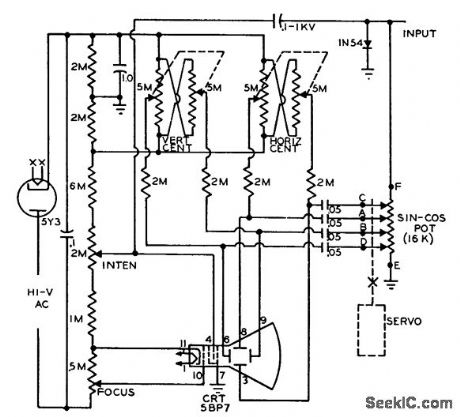
Visual indicator using ordinary cro can be synchronized with rotating directional underwater acoustic transducer, to indicate relative bearing of arriving signal from target. Transducer synchro output, proportional to bearing, drives small servo motor having standard 4-fop sine-cosine potentiometer. Detector output is applied across pot, and four vector outputs are fed to cathode-ray deflection plates. A-c voltage produces rotating bar, and diode clipping of half the signal converts bar to pointer emanating from center of screen. With target signal present, input amplitude is adjusted to produce line from center to edge of screen.-Target Bearing Indicator, Electronic Circuit Design Handbook, Mactier Pub. Corp., N.Y., 1965, p 123.
Reprinted Url Of This Article:
http://www.seekic.com/circuit_diagram/Electrical_Equipment_Circuit/SONAR_BEARING_INDICATOR.html
Print this Page | Comments | Reading(3)

Article Categories
power supply circuit
Amplifier Circuit
Basic Circuit
LED and Light Circuit
Sensor Circuit
Signal Processing
Electrical Equipment Circuit
Control Circuit
Remote Control Circuit
A/D-D/A Converter Circuit
Audio Circuit
Measuring and Test Circuit
Communication Circuit
Computer-Related Circuit
555 Circuit
Automotive Circuit
Repairing Circuit
Code: