Electrical Equipment Circuit
Enable_and_disable_timing_tests
Published:2009/7/23 23:53:00 Author:Jessie | From:SeekIC

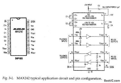
Figure 3-L shows the typical application circuit and pin configuration for the MAX242. This IC is similar to the MAX220, except that the receiver channels can be enabled and disabled, and all four channels can be shut down by external signals. Figures 3-M and 3-N show test circuits and waveforms for receiver-channel enable/disable, and transmitter-channel disable timing.
Reprinted Url Of This Article:
http://www.seekic.com/circuit_diagram/Electrical_Equipment_Circuit/Enable_and_disable_timing_tests.html
Print this Page | Comments | Reading(3)

Article Categories
power supply circuit
Amplifier Circuit
Basic Circuit
LED and Light Circuit
Sensor Circuit
Signal Processing
Electrical Equipment Circuit
Control Circuit
Remote Control Circuit
A/D-D/A Converter Circuit
Audio Circuit
Measuring and Test Circuit
Communication Circuit
Computer-Related Circuit
555 Circuit
Automotive Circuit
Repairing Circuit
Code: