Electrical Equipment Circuit
ENCODER_COMMUTATOR
Published:2009/7/23 22:35:00 Author:Jessie | From:SeekIC

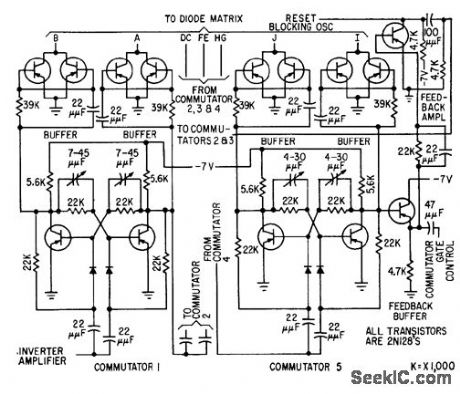
Commutator, buffer, und feedback circuits are given for elapsed-time encoder. After oscillator has triggered 24 elapsed-time counters during storage period, oscillator is switched to electronic commutator controlling diode matrix switch. Counter data is then read out serially through matrix and fed to crt for photo-graphing.-R. J. Kelso and J. C. Groce, Encoder Measures Random Event Time Intervals, Electronics, 32:12, p 48-51.
Reprinted Url Of This Article:
http://www.seekic.com/circuit_diagram/Electrical_Equipment_Circuit/ENCODER_COMMUTATOR.html
Print this Page | Comments | Reading(3)

Article Categories
power supply circuit
Amplifier Circuit
Basic Circuit
LED and Light Circuit
Sensor Circuit
Signal Processing
Electrical Equipment Circuit
Control Circuit
Remote Control Circuit
A/D-D/A Converter Circuit
Audio Circuit
Measuring and Test Circuit
Communication Circuit
Computer-Related Circuit
555 Circuit
Automotive Circuit
Repairing Circuit
Code: