
Basic Circuit
Index 76
Very simple Delay circuit
Published:2012/9/16 21:21:00 Author:Ecco | Keyword: simple Delay

The two circuits di atas illustrate opening a relay contact a short time after the ignition or ligh switch is turned off. The capacitor is charged and the relay is closed when the voltage at the diode anode rises to 12 volts. The circuit on the left is a common collector or emitter follower and has the advantage of one less part since a resistor is not needed in series with the transistor base. However the voltage across the relay coil will be two diode drops less than the supply voltage, or about 11 volts for a 12.5 volt input. (View)
View full Circuit Diagram | Comments | Reading(1014)
AVR Microcontroller Digital Clock with ATtiny2313
Published:2012/9/16 21:19:00 Author:Ecco | Keyword: AVR Microcontroller , Digital Clock

Usually we see Digital clock on LCD or 7 segmen. But, this AVR Digital Clock which is designed by Ficara Emilio displayed on Oscilloscope. The project use ATtiny 2313 as the main controller. What an interesting microcontroller project. Source code and schematic available for download. (View)
View full Circuit Diagram | Comments | Reading(2270)
Digital Clock circuit with CMOS 4047
Published:2012/9/16 21:18:00 Author:Ecco | Keyword: Digital Clock, CMOS

This circuit provides a digital square wave that can be viewed directly or used to drive other circuits. It used the CMOS 4047 Low-Power Monostable/Astable Multivibrator. As used in Tom Duncan's Adventures with Digital Electronic's Book, to drive CMOS Decade of 4-bit binary counters. (View)
View full Circuit Diagram | Comments | Reading(1525)
Digital Up-Down Counter with CD40110BE
Published:2012/9/16 20:52:00 Author:Ecco | Keyword: Digital Up-Down Counter

This circuit board design uses a CD40110BE, and Up/Down Counter ICs. The CD40110BE is a dual-clocked up/down counter with a special preconditioning circuit that allows the counter to be clocked, via posting going inputs, up or down regardless of the state or timing of the other clock line. (View)
View full Circuit Diagram | Comments | Reading(4707)
Delay circuit with NE555 timer
Published:2012/9/13 21:43:00 Author:Ecco | Keyword: Delay circuit , timer

This circuit design was used to switch on device via a LED photocell arrangement (optocoupler) using components R1, C1, D1 and Q1. It produces a delay on powering up to ensure correct sequencing of certain equipment. A very simple delay timer using a single transistor and an R-C timing circuit. (View)
View full Circuit Diagram | Comments | Reading(4317)
Binary Counter using 555 and 4042B
Published:2012/9/13 21:29:00 Author:Ecco | Keyword: Binary Counter
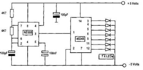
In this circuit diagram, an NE555 timer is used as a pulse generator producing pulses at about one-second duration. This is governed by the timing components connected to pins 2, 6, and 7. If the 100μF capacitor connected on pins 2 and 6 were reduced to 47μF, then the counting pulses will be about 1/2 second each. The output of the pulse generator at pin 3 is connected to pin 1 of the binary counter 4042B. The actual device is a 4042 but are usually advertised as CD4042BE, CD 4042BM, CD 4042BC and so on, but as far as we are concerned in this application they are all the same and will give the same results..... (View)
View full Circuit Diagram | Comments | Reading(3152)
Car windshield wiper delay
Published:2012/9/13 21:26:00 Author:Ecco | Keyword: Car, windshield wiper, delay

The circuit provides a windshield wiper delay, dynamic braking and windshield wipers when they reach the rest position. This prevents the blades passing, which could lead them to stop at a point where they interfere with the vision of drivers. With the original wiper switch off, switch turns on the MLS delay circuit and disconnects the wiring SIB from automobiles. When SI is turned off, the original wiring system and controls the delay circuit is bypassed.
(View)
View full Circuit Diagram | Comments | Reading(2714)
CAR IMMOBILIZER CIRCUIT
Published:2012/9/13 21:25:00 Author:Ecco | Keyword: CAR IMMOBILIZER

A flip of 51 puts the system in action. Power for the circuit is captured from the ignition switch, and circuit receives no power until the ignition switch is closed. When the camera is turned on, the capacitor C1 is charged and the emitter follower Darlington pair (formed by Q1 and Q2) are cut, so no voltage is applied to the relay (Kl), which serves as a load QL transmitter. normally open relay contacts are connected through the points of the vehicle. (At this point, the relay contacts are open and have no effect on the ignition system). Cl charges through R, causing the voltage at the base of Ql to rise steadily.
Source: NEXT.GR (View)
View full Circuit Diagram | Comments | Reading(3155)
Metal locator with Ic4093
Published:2012/9/13 21:13:00 Author:Ecco | Keyword: Metal locator
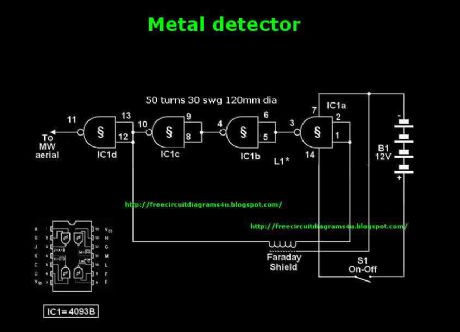
This circuit needs a a Faraday shield, which is connected to 0V.To make this one wrap a tin foil around the coil.and connect to 0v.Then you can use this circuit for find metal.Tune your mw radio until whistle sound comes.
Source: NEXT.GR (View)
View full Circuit Diagram | Comments | Reading(1634)
Water Softener Circuit
Published:2012/9/13 20:53:00 Author:Ecco | Keyword: Water Softener
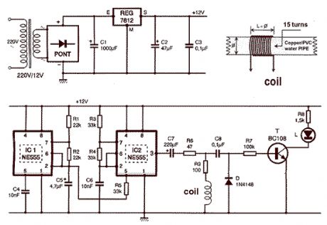
That circuit is based at a technique to remove or neutralize the salt in water, and protect the pipes at home as well as the washing machines or our selves from salt. Its called water softener and its automated circuit using two 555 timers.
Source: NEXT.GR (View)
View full Circuit Diagram | Comments | Reading(5766)
TV and FM jammer schematic
Published:2012/9/13 20:45:00 Author:Ecco | Keyword: TV, FM jammer
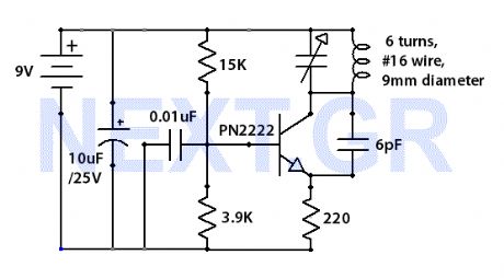
The Jammer is a very small circuit and can fit inside a small plastic box with 9V battery inside. It can be very illegal if you attach an external antenna so don't. adjust frequency by turning trimmer.
Source: NEXT.GR (View)
View full Circuit Diagram | Comments | Reading(5038)
In-Car lights delay circuit
Published:2012/9/13 20:39:00 Author:Ecco | Keyword: In-Car lights, delay circuit

This circuit switch slowly on and off the internal lights in a car. The delaying time can be adjusted changing the values of the 10k, 4M7 resistors and capacitor.
Source: NEXT.GR (View)
View full Circuit Diagram | Comments | Reading(1851)
Passive subwoofer filter
Published:2012/9/13 20:38:00 Author:Ecco | Keyword: Passive subwoofer, filter

The schematic shown, does no need any power supply because is a simple low frequency passive filter. It could be usefull if you want to drive an extra subwoofer from your stereo system.
Source: NEXT.GR (View)
View full Circuit Diagram | Comments | Reading(0)
Free energy collector circuit
Published:2012/9/13 3:52:00 Author:Ecco | Keyword: Free energy collector

This circuit converts surrounding radio frequency waves to electric power. It can provide 40 Volts at 10 Watts indefinitely. The output power can be improved playing with the antenna. Placing the antenna near large metal objects gives more power. Antenna should be more than 150 feet long wire, placed horizontally as high as you can for best results. The pointing direction also is critical to the output. Keep the circuit as close to antenna as posible. You can also experiment with dishes etc. The circuit also acts as a passive detector. When large metal objects passes the power gets higher. Also its sensitivity can detect energy changes on earth and so it can used as early warning of seismic activity.
Source: NEXT.GR (View)
View full Circuit Diagram | Comments | Reading(4889)
Switching Regulator with L4972A
Published:2012/9/13 3:51:00 Author:Ecco | Keyword: Switching Regulator
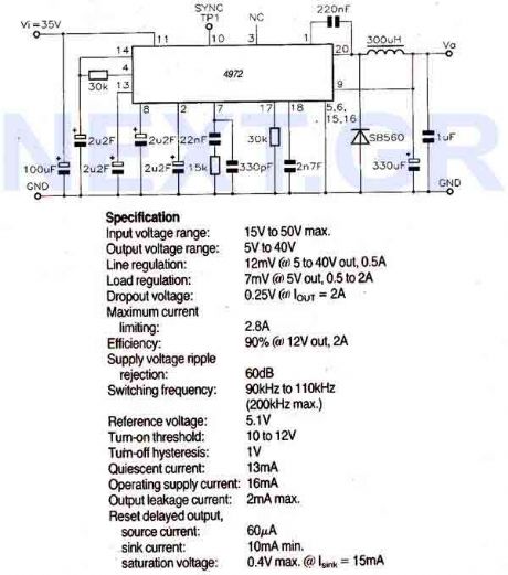
The LA9472A is a 2A monolithic step down switching regulator operating in continuous mode and realized in a new BCD technology allowing the integration of isolated, vertical DMOS power transistors with mixed CMOS/bipolar transistors. The device can deliver 2A at an output voltage adjustable from 5.1V to 40V and contains diagnostic and control functions that make it particularly suitable for microprocessor based systems.
Source: NEXT.GR (View)
View full Circuit Diagram | Comments | Reading(621)
Active double secondary band-pass filter circuit
Published:2012/9/13 1:40:00 Author:Ecco | Keyword: Active double, secondary band-pass filter

The center frequency is 1kHz, quality factor Q=50, gain KV=100( about 40dB).
(View)
View full Circuit Diagram | Comments | Reading(943)
DC series motor commutation circuit
Published:2012/9/13 1:37:00 Author:Ecco | Keyword: DC series , motor commutation

The communication method of series excitation motor is to individually change the armature current or the current direction of the excitation coil individually, then it can achieve the change of rotation direction. The circuit is shown as the figure, the figure (a) is a schematic diagram of the series excited motor, and figure (b) is a series motor commutation circuit diagram.
(View)
View full Circuit Diagram | Comments | Reading(1432)
Antenna tunning circuit for 27MHz CB band
Published:2012/9/12 21:13:00 Author:Ecco | Keyword: Antenna tunning, 27MHz CB band
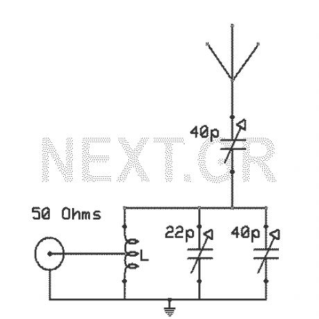
The antenna tunning circuit can accommodate 1/2 wave length antennas or higher, for input resistances of 50 Ohms which make it suitable for CB (Citizen Band) transceivers. C1 is for fine tunning and C2 is just for tunning. Turning C3 with the help of C2 you can set the SWR to 1:1. The Coil L is made of 11 turns of insulated copper wire with diameter of 1mm.
Source: NEXT.GR (View)
View full Circuit Diagram | Comments | Reading(1370)
Simple Coil-less AM receiver
Published:2012/9/12 20:52:00 Author:Ecco | Keyword: Simple , Coil-less , AM receiver
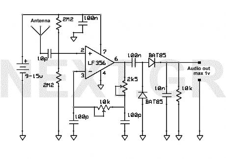
This AM receiver is working perfectly without the need of coils or even a variable capacitor. The LF356 is the basic component. P1 and P2 are the frequency selectors. Use a small telescopic antenna. The stations selectivity is not perfect but is acceptable. (View)
View full Circuit Diagram | Comments | Reading(2407)
Anti-RF filtered power supply 12-14 Volt / 3A
Published:2012/9/12 20:50:00 Author:Ecco | Keyword: Anti-RF , filtered , power supply, 12-14 Volt / 3A

This power supply is dedicated for use with rf equipments like, linear amplifiers, transmitters, receivers, and in every application that clean an-noisy signal is required. The circuit is very simple and you can drive it with a 220V/18V/3A transformer at the pins 1and 2. (View)
View full Circuit Diagram | Comments | Reading(969)
| Pages:76/471 At 206162636465666768697071727374757677787980Under 20 |
Circuit Categories
power supply circuit
Amplifier Circuit
Basic Circuit
LED and Light Circuit
Sensor Circuit
Signal Processing
Electrical Equipment Circuit
Control Circuit
Remote Control Circuit
A/D-D/A Converter Circuit
Audio Circuit
Measuring and Test Circuit
Communication Circuit
Computer-Related Circuit
555 Circuit
Automotive Circuit
Repairing Circuit