
Basic Circuit
Index 79
SOLID STATE RELAY REQUIRES ONLY 50uA DRIVE CURRENT
Published:2012/9/9 21:04:00 Author:Ecco | Keyword: SOLID STATE, RELAY , REQUIRES, ONLY 50uA , DRIVE CURRENT

This circuit demands a control current that is 100 times smaller than that needed by a typical optically isolated solid state relays. It is ideal for battery-powered systems. Using a combination of a high current TRIAC and a very sensitive low current SCR, the circuit can control about 600 watts of power to load while providing full isolation and transient protection.
Source: discovercircuits (View)
View full Circuit Diagram | Comments | Reading(1019)
OPTICAL INTERRUPTER DRAWS MICROAMPS
Published:2012/9/9 21:03:00 Author:Ecco | Keyword: OPTICAL, INTERRUPTER, DRAWS MICROAMPS

This circuit is great for battery-powered systems that use slotted type optical interrupters. It draws only 10uA from a 3v battery that should allow up to 5 years of operation from a lithium battery.
Source: discovercircuits (View)
View full Circuit Diagram | Comments | Reading(2791)
LINE POWERED XENON FLASH TRANSMITTER
Published:2012/9/9 21:02:00 Author:Ecco | Keyword: LINE POWERED , XENON FLASH , TRANSMITTER

This line powered xenon flash circuit drives a small camera type flash tube. It has an optical isolator to allow the flash to be safely triggered from some remote device. A flash rate of 2Hz is possible with the circuit.
Source: discovercircuits (View)
View full Circuit Diagram | Comments | Reading(3977)
Very Loud 3v Powered Beeper -- August 16, 2009
Published:2012/9/9 21:00:00 Author:Ecco | Keyword: Very Loud , 3v, Powered Beeper

Getting a high sound intensity from a piezoelectric type beeper is not easy when the available DC supply is only 3v. The circuit below is not only efficient but produces a very intense sound. The circuit combines a voltage boost section with a resonant feedback network. The voltage applied to the piezoelectric wafer is about 40 volts peak to peak. The result is a circuit that generates an attention getting sound without drawing a lot of current.
Source: discovercircuits (View)
View full Circuit Diagram | Comments | Reading(884)
PRECISION AC PEAK DETECTOR
Published:2012/9/9 20:55:00 Author:Ecco | Keyword: PRECISION, AC PEAK , DETECTOR

This unique circuit uses a very inexpensive voltage comparator to form a peak detector. The DC voltage produced tracks the positive peak of the input signal. It works from about ten millivolts to about 10 volts peak to peak. The maximum frequency is about 150KHz.
Source: discovercircuits (View)
View full Circuit Diagram | Comments | Reading(4787)
Reduced Power Relay Driver
Published:2012/9/9 20:54:00 Author:Ecco | Keyword: Reduced Power , Relay Driver

Relays can handle a lot of power. However, for certain power sensitive designs you would like to reduce the power needed to hold a relay closed. The circuit below performs such a task. It uses a single CD4093 quad NAND gate. When the ?on? logic input signal is detected, the relay is first pulsed on for about 500ms. This is sufficient time to insure the relay is fully closed. After that initial pulse the relay is then driven with a square wave signal, whose duty cycle can be adjusted. The signal duty cycle can be adjusted from about 10% to 90%. In most cases a 50% duty cycle will hold the relay closed. This reduces the average DC current required by the same factor, which means a 4:1 reduction in power. The circuit can operate over a wide 3v to 15v range.
Source: discovercircuits (View)
View full Circuit Diagram | Comments | Reading(611)
VOLTAGE TO FREQUENCY CONVERTER + 1uS LED PULSE DRIVER
Published:2012/9/9 20:54:00 Author:Ecco | Keyword: VOLTAGE TO FREQUENCY CONVERTER , + 1uS , LED PULSE DRIVER

This circuit receives the signal from the above amplifier and launches powerful 1uS infrared light pulses from a low cost LED that are frequency modulated by the audio information. The 10KHz center frequency of the pulse stream is low enough so a standard infrared LED can emit ten times more light than conventional long pulse techniques. The circuit is described in more detail in the transmitter section of my Handbook of Optical Through the Air Communications.
Source: discovercircuits (View)
View full Circuit Diagram | Comments | Reading(2746)
CMOS SCHMITT TRIGGER IC MAKES VCO
Published:2012/9/9 20:51:00 Author:Ecco | Keyword: CMOS, SCHMITT TRIGGER, IC, VCO
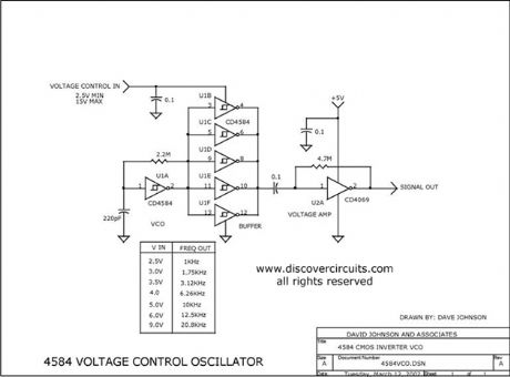
By changing the supply voltage fed to a classic 4584 Schmitt trigger type oscillator, the oscillator frequency can be changed over a range of 50:1. A 74HCU04 inverter is used at the output of the 4584 to maintain a constant TTL logic level signal.
Source: discovercircuits (View)
View full Circuit Diagram | Comments | Reading(2105)
DC motor drive with automatic brake
Published:2012/9/9 20:36:00 Author:Ecco | Keyword: DC motor, drive , automatic brake
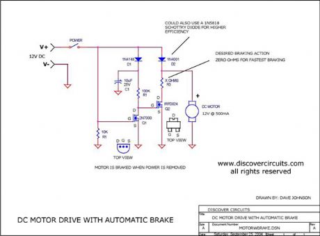
Motor Brake
Source: discovercircuits (View)
View full Circuit Diagram | Comments | Reading(989)
D-FLIP/FLOP ONE SHOT CIRCUITS
Published:2012/9/9 20:32:00 Author:Ecco | Keyword: D-FLIP/FLOP, ONE SHOT CIRCUITS
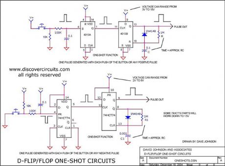
Yes you can use cheap D flip/flop logic circuits as nice one-shot pulse generators. This schematic shows how the popular CD4013 and the CD74HC74 can be used to generate pulses ranging from nanoseconds to seconds.
Source: discovercircuits (View)
View full Circuit Diagram | Comments | Reading(2783)
Fridge neon multi-point status indicator circuit
Published:2012/9/6 22:43:00 Author:Ecco | Keyword: Fridge neon , multi-point , status indicator
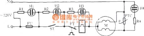
In the figure, M is the refrigerator compressor motor. H1 ~ H4 are neon lamps, R1 ~ R4 arelimiting resistors. FU is fuse, ST is the thermostat, FT is the overload protector, PTC is thestarter. Multi- point action or failure is displayed by neon, and theline is simple and convenient to identify.
(View)
View full Circuit Diagram | Comments | Reading(701)
Bidirectional thyristor power consumption brake circuit
Published:2012/9/6 22:22:00 Author:Ecco | Keyword: Bidirectional thyristor , power consumption , brake
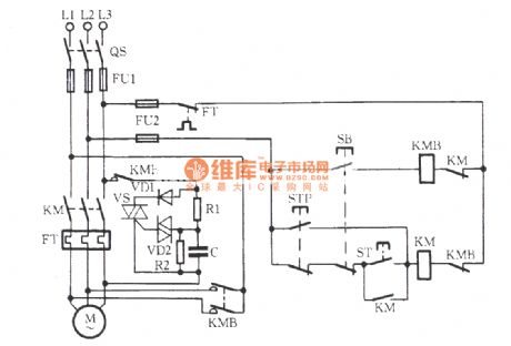
As shown in the figure, VS is the bidirectional thyristor, and its conduction angle determines the size of the braking energy; VD2 is the trigger tube, the 30V breakdown voltage enables VS reliable and stable trigger. VD1 is the rectifier diode, R2 is bleeder resistor to make the charge on the C be discharged at any time. R1, C form the phase shifting circuit to control the VS conduction angle, thereby providing an appropriate size of pulsating DC voltage for braking. C takes higher value, the braking time is longer; Conversely, the braking time is shorter. People can select appropriate capacitance of C to make brake average voltage be 85V, the brake current be 4.5 ~~ 5A, motor full load brake time be 4 to 5 seconds. KM is the main contact for the operation of the motor M, KMB is brake contactor of motor M.
(View)
View full Circuit Diagram | Comments | Reading(1757)
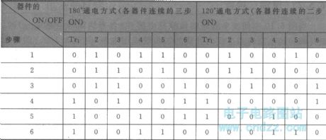
Inverter circuit ( three - phase bridge circuit )
Published:2012/9/6 21:28:00 Author:Ecco | Keyword: Inverter , three - phase bridge
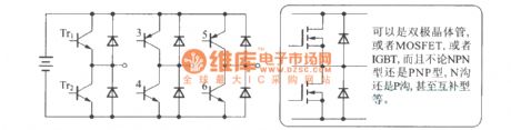
It can be a bipolar transistor, or MOSFET, or IGBT, NPN or PNP, N- channel or P-channel, and even complementary.
Basic switching sequence of the three - phase inverter is shown asfollowing (if the order is reversed , then the motoris reversed, too. Theswitch combination with the DC converter and invertercan adjust the voltage).
(View)
View full Circuit Diagram | Comments | Reading(1660)
FLASHING LED POWER INDICATOR DRAWS LOW CURRENT .
Published:2012/9/6 20:37:00 Author:Ecco | Keyword: FLASHING LED, POWER INDICATOR, DRAWS LOW CURRENT

This circuit flashes a power indicator LED to keep the average current low.
Source: discovercircuits (View)
View full Circuit Diagram | Comments | Reading(2439)
Incandescent Lamp Inrush Current Limiter
Published:2012/9/6 20:34:00 Author:Ecco | Keyword: Incandescent Lamp, Inrush Current Limiter

This circuit limits the large inrush current often associated with large incandescent lamps. With the components shown the current is limited to 1 amp, but it could be scaled to any desired current.
Source: discovercircuits (View)
View full Circuit Diagram | Comments | Reading(4494)
Low Voltage H-bridge
Published:2012/9/6 20:23:00 Author:Ecco | Keyword: Low Voltage, H-bridge

TTL type Q and inverted Q inputs control a classic H-bridge circuit, rated at 50 volts and about 10 amps. The circuit can control power and direction of a DC motor.
Source: discovercircuits (View)
View full Circuit Diagram | Comments | Reading(2404)
Electrical Device Harvests Earthworms
Published:2012/9/6 20:22:00 Author:Ecco | Keyword: Electrical Device, Harvests Earthworms

A 120vac or 240vac isolation transformer is used to force earthworms from the ground.
Source: discovercircuits (View)
View full Circuit Diagram | Comments | Reading(723)
High Impedance JFET Buffers
Published:2012/9/6 20:14:00 Author:Ecco | Keyword: High Impedance, JFET Buffers

I have used these circuits many times. They are great when you need a low gain AC signal amplifier with a very high input impedance. It is good to beyond 50MHz. (View)
View full Circuit Diagram | Comments | Reading(2524)
Charge Coupled MOSFET Relay
Published:2012/9/6 20:12:00 Author:Ecco | Keyword: Charge Coupled , MOSFET Relay

This circuit acts as an AC/DC relay with a rating up to 50 volts peak and up to 10 amps of current. The differential oscillator supplies voltage to the gates of the two FETs with good isolation will drawing only 1.5ma of current.
Source: discovercircuits (View)
View full Circuit Diagram | Comments | Reading(1046)
Medium Power 40KHz Ultrasound Transducer Driver
Published:2012/9/6 20:09:00 Author:Ecco | Keyword: Medium Power, 40KHz , Ultrasound Transducer Driver

This crystal controlled circuit drives a 40KHz piezoelectric transducer with a 30v peak to peak signal.
Source: discovercircuits (View)
View full Circuit Diagram | Comments | Reading(4531)
| Pages:79/471 At 206162636465666768697071727374757677787980Under 20 |
Circuit Categories
power supply circuit
Amplifier Circuit
Basic Circuit
LED and Light Circuit
Sensor Circuit
Signal Processing
Electrical Equipment Circuit
Control Circuit
Remote Control Circuit
A/D-D/A Converter Circuit
Audio Circuit
Measuring and Test Circuit
Communication Circuit
Computer-Related Circuit
555 Circuit
Automotive Circuit
Repairing Circuit