
Basic Circuit
Index 78
MSC1210 Reset Circuit
Published:2012/9/10 21:27:00 Author:Ecco | Keyword: Reset

According to the MSC1210 datasheet, you will perform an external reset by taking RST pin high for two tOSC periods as this stops device operation, crystal oscillation, causes all digitall pins to be pulled high from that point and then followed by taking the RST pin low that initiates the reset procedure. (View)
View full Circuit Diagram | Comments | Reading(959)
Gain buffer circuit
Published:2012/9/10 21:12:00 Author:Ecco | Keyword: Gain buffer

The difference between these amplified signals is used to set the 's bias and hence Ql Q2 current channel. This Ql forces of V GS at all that is required voltage corresponding to the circuit input and potential output. The capacitor of 2000 pF to Al provides stable loop compensation. The RC network at the output of Amnesty International that it obscures the edges at high speed coupled through Q2 's base-collector junction. A2 exit from the east also returned to the screen around Ql cause the door, the boot capacity of the circuit comes into force unless I pF.
Source: discovercircuits (View)
View full Circuit Diagram | Comments | Reading(738)
2 to 4 wire audio converter
Published:2012/9/10 21:04:00 Author:Ecco | Keyword: 2 to 4 wire , audio converter

This audio converter circuit maintains 40 dB of isolation between the two halves of entry and exit of a four-line son, while allowing a line connecting two son. A balancing potentiometer, R, adjusts the gain of zero lC2to crossing the inlet to the outlet.
Source: discovercircuits (View)
View full Circuit Diagram | Comments | Reading(3460)
Audio compressor circuit
Published:2012/9/10 20:57:00 Author:Ecco | Keyword: Audio compressor
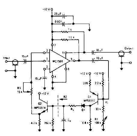
The amplifier drives the base of a common emitter PNP MPS6517 operating with a voltage gain of about 20. RL control varies the quiescent point of the transistor Q, so that varying amounts of signal exceed the level of V r, diode D 1 rectifies the positive peaks Ql output is only when these peaks are more larger than r V ' 7. 0 volts. The result is filtered ex Rx. s, controls the charging time constant or time of attack. Cx is involved in two loading and unloading. R2 (150 K, the input resistance of the emitter-follower Q2) controls the decay time.
Source: discovercircuits (View)
View full Circuit Diagram | Comments | Reading(4791)
Q-multiplier filter circuit
Published:2012/9/10 20:56:00 Author:Ecco | Keyword: Q-multiplier, filter

This circuit is selective for the tuning adjustment between two closely spaced tones audio. The frequency is dependent on the selective value capacitors and resistors in the feedback circuit between the collector and base of Q1. With the values shown, the frequency can be tuned to a hundred cycles or so-around 650 Hz Ri and R2 should be grouped. R3 potentiometer transmitter determines the sharpness of the response curve.
Source: discovercircuits (View)
View full Circuit Diagram | Comments | Reading(2762)
Active crossover circuit with TL074
Published:2012/9/10 20:55:00 Author:Ecco | Keyword: Active crossover

An audio source, like a mixer, preamp, EQ, or a recorder, is fed to the input of the Electronic Crossover Circuit. This signal is either AC or coupling, depending on the setting of switch 51, the non-inverting input of buffer amplifier Ul-a, a section of a quad BIFET, low amp TL074 noise made by Texas Instruments op. This stage has a gain of 2, and its output is distributed to both a low pass filter made by R4, R5, C2, C3, and Uld op-amp, and a high-pass filter made by R6, R7, C4 , C5, and op amp ULC. These are12 dB / octave Butterworth filters. The response of the Butterworth filter was chosen because it gives the best compromise between the damping and phase.
Source: discovercircuits (View)
View full Circuit Diagram | Comments | Reading(5004)
40KHz Ultrasound Receiver
Published:2012/9/10 20:46:00 Author:Ecco | Keyword: 40KHz , Ultrasound Receiver

A X100 transistor amplifier is followed by a zero cross detector circuit, using a voltage comparator. The output is a TTL logic signal, corresponding to the received 40KHz signal.
Source: discovercircuits (View)
View full Circuit Diagram | Comments | Reading(2523)
VIDEO SIGNAL EDGE ENHANCEMENTS
Published:2012/9/10 20:37:00 Author:Ecco | Keyword: VIDEO SIGNAL, EDGE ENHANCEMENTS

I designed this circuit many years ago, based on the claims that the technique would improve the quality of standard TV images. The circuit adds information to the edges of the objects and was reported to bring out more detail. After building and testing the circuit, I could definitely see a difference between it and a regular TV display but I don?t think most people would go to the trouble of installing the circuit for only a marginal improvement. Still, it is an interesting circuit with which someone might experiment.
Source: discovercircuits (View)
View full Circuit Diagram | Comments | Reading(618)
40KHz TV-VCR LIGHT SOURCE REPEATER
Published:2012/9/10 20:36:00 Author:Ecco | Keyword: 40KHz, TV-VCR, LIGHT SOURCE REPEATER

This circuit is designed to be placed directly in front of a standard TV or VCR remote. The exiting light pulses produced by the circuit match the pulses from the remote but are about 10 times more powerful. Using the device, the remote can operate a TV or VCR over three times the normal distance.
Source: discovercircuits (View)
View full Circuit Diagram | Comments | Reading(2124)
Audio Signal Detector Switch
Published:2012/9/10 20:26:00 Author:Ecco | Keyword: Audio Signal, Detector, Switch

This circuit will activate a transistor switch when it detects at least 50mv peak to peak of an audio signal. It could be used to turn on a relay, routing the signal to were it is needed.
Source: discovercircuits (View)
View full Circuit Diagram | Comments | Reading(2863)
ELECTRIC FIELD DISTURBANCE MONITOR - Alarm Discriminator + Battery Monitor
Published:2012/9/10 20:17:00 Author:Ecco | Keyword: ELECTRIC FIELD , DISTURBANCE MONITOR, Alarm Discriminator, Battery Monitor

This schematic is the power supply and front-end sections of the field monitor that is discussed in more detail at Electric Field Disturbance Monitor. The system can detect human and animal motion by the electric fields they disturb.
Source: discovercircuits (View)
View full Circuit Diagram | Comments | Reading(2613)
Reduced Power Relay Driver Aug 3, 2008
Published:2012/9/10 20:13:00 Author:Ecco | Keyword: Reduced Power , Relay Driver

Relays can handle a lot of power. However, for certain power sensitive designs you would like to reduce the power needed to hold a relay closed. The circuit below performs such a task. It uses a single CD4093 quad NAND gate. When the ?on? logic input signal is detected, the relay is first pulsed on for about 500ms. This is sufficient time to insure the relay is fully closed. After that initial pulse the relay is then driven with a square wave signal, whose duty cycle can be adjusted. The signal duty cycle can be adjusted from about 10% to 90%. In most cases a 50% duty cycle will hold the relay closed. This reduces the average DC current required by the same factor, which means a 4:1 reduction in power. The circuit can operate over a wide 3v to 15v range.
Source: discovercircuits (View)
View full Circuit Diagram | Comments | Reading(657)
Three-phase motor △ low-speed operation circuit
Published:2012/9/10 1:31:00 Author:Ecco | Keyword: Three-phase motor , low-speed operation

Sometimes the motor is required to run at low speed or without borrowing mechanical gearbox, the effect can be realized by the circuit shown as the figure. From the figure, three-phase windings are connected VD1~VD3 respectively, then people can press normally open contact KM2, ST1, then KM1l pulls in, VD1, VD2 VD3 are connected to winding, motor M start running at low speed. And then pressing ST2, KM2 pulls in, VD1, VD2 VD3 are shorted, M runs at full speed under rated voltage.
(View)
View full Circuit Diagram | Comments | Reading(2003)
Reflected Infrared Light Switch
Published:2012/9/9 21:20:00 Author:Ecco | Keyword: Reflected , Infrared Light, Switch

Infrared light reflected off a finger is used to activate this switch circuit. Drawing only 30uA from a 3v supply, this circuit will detect a human finger with a range of about 1 inch. The sensor uses an inexpensive infrared LED and a matching photo diode.
Source: discovercircuits (View)
View full Circuit Diagram | Comments | Reading(1986)
Home Made Geophone Detects Foot Stomp
Published:2012/9/9 21:17:00 Author:Ecco | Keyword: Home Made, Geophone, Detects, Foot Stomp

A home made geophone is made from a strong magnet, a coil of wire and a rubber band. The circuit is sensitive enough to detect the vibrations of a nearby foot stomp. It could be used as an earthquake detector.
Source: discovercircuits (View)
View full Circuit Diagram | Comments | Reading(5282)
PRECISION FULLWAVE RECTIFIER
Published:2012/9/9 21:13:00 Author:Ecco | Keyword: PRECISION, FULLWAVE RECTIFIER

I have used this handy circuit many times. It accurately converts an AC signal into pulsing DC, which can be filtered to provide an average of the input voltage. It works from millivolts to volts. The circuit shown requires a stable +5v reference if a single power supply is used.
Source: discovercircuits (View)
View full Circuit Diagram | Comments | Reading(2917)
Circuit Forms Ideal Diode Function
Published:2012/9/9 21:13:00 Author:Ecco | Keyword: Circuit Forms , Ideal , Diode Function

This circuit uses a low power op amp and a p-channel FET to form a diode function with a very low 0.05 volt voltage drop. With the selected FET, the circuit can handle up to 2 amps of current. Higher currents are possible with a FET with a lower channel resistance. The total current drawn by the circuit during operation is a low 20 microamps. The maximum voltage is 15v.
Source: discovercircuits (View)
View full Circuit Diagram | Comments | Reading(3312)
175KHz INDUCTIVE PULSE TRANSMITTER
Published:2012/9/9 21:10:00 Author:Ecco | Keyword: 175KHz , INDUCTIVE, PULSE TRANSMITTER

This circuit is discussed in more detain in the Experimenters Journal. The transmitter?s six-inch diameter coil launches powerful magnetic 175KHz ring pulses that can be detected by the circuit below.
Source: discovercircuits (View)
View full Circuit Diagram | Comments | Reading(1140)
Infrared Safety Switch
Published:2012/9/9 21:09:00 Author:Ecco | Keyword: Infrared , Safety Switch

Using a slotted optical sensor, this circuit can be used as a replacement for a large mushroom pushbutton safety switch.
Source: discovercircuits (View)
View full Circuit Diagram | Comments | Reading(2173)
12v Battery Load Cutout Circuit -- August 23, 2009
Published:2012/9/9 21:08:00 Author:Ecco | Keyword: 12v, Battery Load, Cutout Circuit

Lead-acid batteries should not be discharged below a certain point if they are to last. Also, you don?t want certain 12v powered devices, which might be plugged into a car?s cigarette lighter outlet, to drain the car battery down to a point where the car?s engine will not start. To prevent battery damage or a dead battery, the circuit below disconnects a load from the battery when the voltage dips below a fixed but adjustable voltage and will not reconnect the load until a reset button is pressed. To keep the whole circuit efficient and compact, a medium current rated p-channel FET forms the power switch. A 8.2v zener diode forms the voltage reference while a second 15v zener diode acts as a transient voltage protector.
Source: discovercircuits (View)
View full Circuit Diagram | Comments | Reading(1227)
| Pages:78/471 At 206162636465666768697071727374757677787980Under 20 |
Circuit Categories
power supply circuit
Amplifier Circuit
Basic Circuit
LED and Light Circuit
Sensor Circuit
Signal Processing
Electrical Equipment Circuit
Control Circuit
Remote Control Circuit
A/D-D/A Converter Circuit
Audio Circuit
Measuring and Test Circuit
Communication Circuit
Computer-Related Circuit
555 Circuit
Automotive Circuit
Repairing Circuit