
Basic Circuit
Index 77
Simple light-switch circuit
Published:2012/9/12 20:49:00 Author:Ecco | Keyword: Simple light-switch

The circuit is a light switch who triggers when light drops on photo resistor. It is fairly simple in construction and can be used in a million applications. The photoresistor and the trimmer work as a voltage divider and also polarize the transistor TR1. TR1 triggers TR2 and TR2 drives the relay. Trimmer R7 is for adjusting the sensitivity of the circuit. (View)
View full Circuit Diagram | Comments | Reading(735)
The directly start circuit by change-over switch
Published:2012/9/11 22:37:00 Author:Ecco | Keyword: directly start , change-over switch
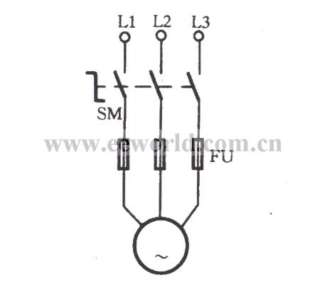
As shown in the diagram, SM is a change-over switch which is also known as combination switch, and the common models inlcudeHZ10, HZ15 series. It has a rotary handleto drive three movable contact pieces rotating at the same time and turn ON or OFF respectively the three pairs of stationary contact pieces.When it isturned on, the motor starts rotating; when it is cut off, the motor M stopsrotating. The circuit isused for the grinders, lathes and other mechanical equipments.
(View)
View full Circuit Diagram | Comments | Reading(1215)
Model Glow Plag driver circuit
Published:2012/9/11 20:58:00 Author:Ecco | Keyword: Model , Glow Plag driver

model airplanes, boats, cars and use of ignition of glow plugs for their miniature (O. Bcc to 15cc) internal combustion engines. These engines happen with the heavy batteries on board, HT coil, and condenser spark required for ignition classic, while simultaneously developing much higher RPM (and thus power) as the compression ignition (diesel) engines . The heart of a candle is a coil of platinum alloy filament heated to start the engine by an external battery, or 1. 5 volts or 2 volts. To complete this battery, a second power supply of 12 volts is often necessary to start the engine, together with a third type 6 volt electric fuel pump. (View)
View full Circuit Diagram | Comments | Reading(1707)
AVR-P40-USB-8535 BOARD FOR AT90S8535
Published:2012/9/11 20:52:00 Author:Ecco | Keyword: AVR-P40-USB-8535 BOARD

There are two ways to program AVR-P40-USB: with ICSP port and with JTAG port. To program via ICSP port you need serial port or parallel port AVR-ICSP programmer dongle (Olimex part # AVR-PG1B or AVR-PG2B). The serial port ICSP programmer (AVR-PG1B) works with PonyProg software by from Claudio Lanconelli and the latest release may be download for free from lancos.com The parallel port ICSP programmer (AVRPG2B) works with AVR ISP from Atmel and may be download for free from Atmels web site. (View)
View full Circuit Diagram | Comments | Reading(1283)
Wireless Keylogger circuit
Published:2012/9/11 20:52:00 Author:Ecco | Keyword: Wireless Keylogger

The Wireless Keylogger consists of two main building blocks: the transmitter, and the receiver. The actual keylogging takes place in the transmitter, which is in fact a PS/2 hardware keylogger, with a built-in 2.4 GHz wireless module. Captured keystroke data is transmitted through the radio-link in real-time, rather than getting stored. The receiver on the other hand, is a wireless acquisition unit with a USB interface. All keystroke data received from the transmitter is sent to the host computer via USB. From the software side, this data is available through a virtual COM port, allowing any terminal client to be used for visualizing keystroke data. (View)
View full Circuit Diagram | Comments | Reading(2902)
Display board to interface it with 8051
Published:2012/9/11 20:51:00 Author:Ecco | Keyword: Display board, interface

74hc573 is used to store data so that the previous content on SS is not vanish when we disable LE pin. T0 select the proper latch 74hc238, 3x8 decoder is used. And to convert BCD into decimal, 74ls48 converter is used. Note that latches U1 to U4 are connected with C.C SS, so the output of 74ls48 will only go to these latches. Whereas latches U6 and U8 are connected to DP oF SS and LEDs respectfully. You can emit these latches i used them to distinguish between various mode i.e, digital clock, stop watch, counter and manual input. (View)
View full Circuit Diagram | Comments | Reading(2421)
Interfacing DS1307 RTC AVR Microcontroller
Published:2012/9/11 20:51:00 Author:Ecco | Keyword: Interfacing, RTC , AVR Microcontroller

Real Time Clocks, as the name suggests are clock modules. They are available as integrated circuits (ICs) and manages timing like a clock. Some RTC ICs also manages date like a calendar. The main advantage is that they have a system of battery backup which keeps the clock/ca lender running even in case of power failure. A very small current is required for keeping the RTC alive. This in most case is provided by a miniature 3v lithium coin cell. So even if the embedded system with RTC is powered off the RTC module is up and running by the backup cell. This same technique is used in PC timing also. If you have opened your computer case you will notice a small coin cell in the mother board. (View)
View full Circuit Diagram | Comments | Reading(2078)
Frequency counter 400Hz to 50MHz with PIC 16F84
Published:2012/9/11 20:49:00 Author:Ecco | Keyword: Frequency counter , 400Hz to 50MHz , PIC

It consists only from Microchip PIC 16F84 cpu and LCD text module. Author states that this counter is capable metering frequencies from 400Hz to 50MHz. I used faster, 20MHz version of 16F84A-20I/P, and it managed to count 80MHz oscillator output. (View)
View full Circuit Diagram | Comments | Reading(7191)
AVR Microcontroller Digital Clock with ATtiny 2313
Published:2012/9/11 20:32:00 Author:Ecco | Keyword: AVR Microcontroller, Digital Clock , ATtiny

Usually we see Digital clock on LCD or 7 segmen. But, this AVR Digital Clock which is designed by Ficara Emilio displayed on Oscilloscope. The project use ATtiny 2313 as the main controller. What an interesting microcontroller project. Source code and schematic available for download. (View)
View full Circuit Diagram | Comments | Reading(2317)
LCD Oscilloscope using AVR MC
Published:2012/9/11 20:32:00 Author:Ecco | Keyword: LCD Oscilloscope, AVR MC

This is one of great project based on AVR microcontroller. It use ATmega 32 as processor and LCD 128x64 pixels for display. If you need to measure low frequency i thought this project, AVR oscilloscope, will be usefull. Maksimum frequency for AVR oscilloscope is 5 kHz (square signal), other signals (sine or triangle) the frequency is lower ( almost 1 kHz) for having clear view of the signal. Voltage input range is 24V AC / 30V DC. (View)
View full Circuit Diagram | Comments | Reading(4678)
Interfacing DRAM M5M44800 Memory with AVR AT90S8515
Published:2012/9/11 20:30:00 Author:Ecco | Keyword: Interfacing DRAM, Memory , AVR

Is it possible to use DRAM with microcontroller AVR? Yes, it is possible. Jesperh has proved it. He hooked up a DRAM to a small processor (in this case an Microcontroller Atmel 8515), and handle the RAS/CAS sequencing and refresh in software. The type of DRAM is Hitatchi M5M44800, a 512k*8 DRAM!. Bigger than the original memory of microcontroller AT90S8515 that is 512 byte RAM. The project use C to programm it. The chip required small power consumption, only takes about 2-3 mA when just refreshing and with a low access rate. (View)
View full Circuit Diagram | Comments | Reading(1150)
Chime Circuit with 4049
Published:2012/9/11 20:20:00 Author:Ecco | Keyword: Chime

Resistor R1, capacitor C1, and two converters form a square wave generator, which produces the basic tone. The generator is sui followed by an inverter which serves as both a buffer and a driver for the President. The resistor R2, which has a minimum value of 100 ohms, limits the power and volume controls. The diode D1, capacitor C2, resistors R3 and R4, and two in converters to create the pulse generator which determines the power-up and decay times of the ring. (View)
View full Circuit Diagram | Comments | Reading(2046)
Pincushion correction circuit -2
Published:2012/9/10 22:59:00 Author:Ecco | Keyword: Pincushion correction

This circuit is part of the Venus D2918 model pincushion correction circuit, and compared to the pincushion correction circuit -1, it also has V951 , V950 two-stage amplifier, the reason is that field sawtooth is not taken from the field deflection coil sampling resistor, but from TDA8838 ( 46) feet, due to its lesser amplitude, it adds the two-stage amplifier.
(View)
View full Circuit Diagram | Comments | Reading(1006)
The threshold switching circuit with TCAl05/TcA205A
Published:2012/9/11 1:45:00 Author:Ecco | Keyword: threshold switching

The maximum operating voltage in the circuit (a) changes from the US = 4.5V ( TCA105) 4.75V ( TCA205A) to 30V. The load here is relay coil. The current flowing load is about 3mA current in the turn-off state and IL = UL / RL ≤ 50mA in the turn-on state.
(View)
View full Circuit Diagram | Comments | Reading(1613)
The lathe no-load automatically shut-down and power - saving circuit 1
Published:2012/9/10 22:52:00 Author:Ecco | Keyword: lathe , no-load, automatically shut-down, power - saving

When the lathe workers operate lathe, the spindle needs to stop rotating, they are accustomed to placing operating lever in the parking position, then they will leave the lathe do other things and ignore to press the stop button, that will waste of energy because of the motor no-load operation for a long time. The circuit shown as the figure can avoide motor from idling.
(View)
View full Circuit Diagram | Comments | Reading(1449)
Single-phase motor impedance with indicator light speed adjusting circuit
Published:2012/9/10 22:45:00 Author:Ecco | Keyword: Single-phase motor, impedance , indicator light, speed adjusting

Asshown in Figure, the circuituses reactor tap to connect withindicator H. When the motor is operating, the two taps of reactor pass current to generate voltage, then the indicator H is lit.
(View)
View full Circuit Diagram | Comments | Reading(1175)
Single-phase motor reactor tap speed adjusting circuit
Published:2012/9/10 22:38:00 Author:Ecco | Keyword: Single-phase motor, reactor tap, speed adjusting

The different speed blocks of reactor L are adjusted by tap and the speed switch. L is connected to the secondary winding LA in series. LR is the primary winding. L provides supply voltage through another winding for indicator H.
(View)
View full Circuit Diagram | Comments | Reading(1000)
Single phase motor electronic stepless thyristor circuit
Published:2012/9/10 22:29:00 Author:Ecco | Keyword: Single phase , motor , electronic , stepless, thyristor

As shown in Figure, adjusting potentiometer RP can adjust the conduction angle of thyristor, and the output voltage is changed, so as to achieve the purpose of stepless speed adjusting of motor. RP resistance is low,and VS has high breakover angle, high output voltage, then motor has high speed; conversely, the high RP resistance makes low speed of the motor.
(View)
View full Circuit Diagram | Comments | Reading(2067)
Passive subwoofer filter
Published:2012/9/10 21:50:00 Author:Ecco | Keyword: Passive , subwoofer filter

The schematic shown, does no need any power supply because is a simple low frequency passive filter. It could be usefull if you want to drive an extra subwoofer from your stereo system. (View)
View full Circuit Diagram | Comments | Reading(4437)
FM IF Subsystem with CA3189E
Published:2012/9/10 21:49:00 Author:Ecco | Keyword: FM IF Subsystem

TheCA3189E is a comprehensive FM-IF system designed for high fidelity FM tuners. It includes a three stage FM-IF amplifier/limiter configuration with level detectors for each stage, a double-balanced quadrature FM detector and an audio amplifier that features the optional use of a muting circuit. The advanced circuit design includes desirable special features such as delayed AGC for the RF tuner, an AFC drive circuit, and an output signal to drive a tuning meter and/or provide stereo switching logic. In addition, internal power supply regulators maintain a nearly constant current drain over the voltage supply range of +8V to +16V. Distortion is primary a function of the phase linearity characteristics of the external detector coil. (View)
View full Circuit Diagram | Comments | Reading(948)
| Pages:77/471 At 206162636465666768697071727374757677787980Under 20 |
Circuit Categories
power supply circuit
Amplifier Circuit
Basic Circuit
LED and Light Circuit
Sensor Circuit
Signal Processing
Electrical Equipment Circuit
Control Circuit
Remote Control Circuit
A/D-D/A Converter Circuit
Audio Circuit
Measuring and Test Circuit
Communication Circuit
Computer-Related Circuit
555 Circuit
Automotive Circuit
Repairing Circuit