
Basic Circuit
Index 65
Square Wave Oscillator
Published:2012/12/3 20:37:00 Author:muriel | Keyword: Square Wave Oscillator

A very basic square wave generator using a CMOS 4011 NAND gate. (View)
View full Circuit Diagram | Comments | Reading(4063)
Quiz Circuit
Published:2012/12/3 0:41:00 Author:muriel | Keyword: Quiz Circuit

View full Circuit Diagram | Comments | Reading(673)
E.S.P. Conjuring Trick
Published:2012/12/3 0:23:00 Author:muriel | Keyword: E.S.P. Conjuring Trick

View full Circuit Diagram | Comments | Reading(676)
The bistable circuit with optocoupler and transistor
Published:2012/12/2 20:37:00 Author:Ecco | Keyword: bistable , optocoupler , transistor
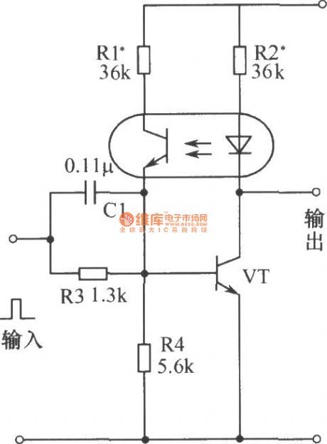
In the initial state with the power turning on, the transistor VT is cutoff, the circuit outputs high potential. When the input terminal is coupled with a positive pulse, the collector current of VT increases, photocoupler light emitting diode emits light, and the collector-emitter resistance of phototransistor becomes smaller, then the base current of VT increases to form a positive feedback, so that VT quickly be saturated, and it changes to 0 from 1 . When it is input the negative pulse, the collector current of VT becomes small, thereby enabling light emitting diode darken, and VT's base current becomes small, causing the collector current of VT to be further reduced, the VT quickly become the OFF state, the light emitting diode does not emit light, the phototransistor is turned off, so that VT is stable in the off state, the state of flip-flop changes from 0 to l .
(View)
View full Circuit Diagram | Comments | Reading(1331)
Pincushion correction circuit 1
Published:2012/11/29 21:08:00 Author:Ecco | Keyword: Pincushion correction
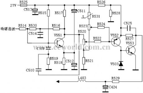
Field sawtooth wave signal is sent into V551's base by R514, then it is integrated by R516 and C514, and E-B differential integrated by C510, R519, C509 and V551 to form parabolic wave signal, then it is amplified by V552 and output from collector, and it is directly sent to V553's base, parabolic wave signal output from V553 collector is added to V402's negative end by R529 and L403 to modulate the current on coil by V401, then the distortion can be corrected.
(View)
View full Circuit Diagram | Comments | Reading(1027)
Pincushion correction circuit 3
Published:2012/11/29 21:13:00 Author:Ecco | Keyword: Pincushion correction
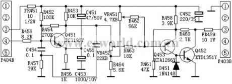
The models using pincushion correction: Korea Samsung MC-15 movement, Venus C6418, V6458, LOWA CT6388W, Peony 64C1. VR451 is the amplitude adjustment potentiometer, VR452 is the Pincushion adjustment potentiometer. Sawtooth voltage is sent to the pincushion correction circuit by P404's pin 4, R455, C454 and R457 form an integrator which integrates sawtooth wave to form a convex parabolic wave voltage.
(View)
View full Circuit Diagram | Comments | Reading(762)
The coupling circuit with optical fiber transmission data
Published:2012/11/29 21:25:00 Author:Ecco | Keyword: coupling circuit , optical fiber , transmission data
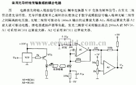
The circuit shown in figure can convert input analog signal into frequency signal by voltage V / F - the frequency converter, then it is sent to the optical fiber by light emitting diode. The length of optical fiber or polystyrene is determined the isolated voltage between the digital or analog signal input terminal and a photodiode. The photodiode can drive operational amplifier A1 with 100mA output.
(View)
View full Circuit Diagram | Comments | Reading(1054)
Typical application circuit of low-power programmable sensor signal processor TSS400-S1/S2
Published:2012/11/23 2:35:00 Author:Ecco | Keyword: Typical application , low-power , programmable , sensor, signal processor

The system uses 3V lithium battery (e), C1 and C2 are power supply decoupling capacitors. Crystal oscillator's frequency selects 32. 768kHz. External memory uses two 512-byte-24C04 E2PROMs. Silicon pressure sensor is shown in the dashed box. It can use temperature compensation software to get measurement accuracy and 12-bit ADC pressure value. Analog lines in the figure is connected to USDD-end, the sensor can only get power supply in a/d conversion, and it can save electricity consumption of the entire system.
(View)
View full Circuit Diagram | Comments | Reading(961)
Isolated data acquisition system circuit with 5 channel low power programmable sensor signal processor AD7714 and microprocessor circuit
Published:2012/11/23 1:11:00 Author:Ecco | Keyword: Isolated , data acquisition system , 5 channel, low power, programmable sensor, signal processor , microprocessor

AD7714 is suitable for low-power, narrow bandwidth, high resolution data acquisition system. 3-wire serial interface allows the data acquisition system to use 3 light couplers for isolation. If AD7714 analog input input signal is positive, the entire system can use +3V or +5V single-supply.
(View)
View full Circuit Diagram | Comments | Reading(698)
Dual Regulated PSU
Published:2012/11/23 1:06:00 Author:muriel | Keyword: Dual , Regulated PSU

View full Circuit Diagram | Comments | Reading(648)
Unregulated PSU
Published:2012/11/23 1:05:00 Author:muriel | Keyword: Unregulated PSU

A basic full wave rectified power supply is shown below. The transformer is chosen according to the desired load. For example, if the load requires 12V at 1amp current, then a 12V, 1 amp rated transformer would do. However, when designing power supplies or most electronic circuits, you should always plan for a worst case scenario. With this in mind, for a load current of 1 amp a wise choice would be a transformer with a secondary current rating of 1.5 amp or even 2 amps. Allowing for a load of 50% higher than the needed value is a good rule of thumb. The primary winding is always matched to the value of the local electricity supply. (View)
View full Circuit Diagram | Comments | Reading(778)
LF Crystal Controlled Oscillator
Published:2012/11/23 0:42:00 Author:muriel | Keyword: LF Crystal, Controlled Oscillator

The RF engineer sometimes has to look for an instrument that will check a low frequency quartz crystal unit reliably and rapidly. This is a difficult piece of equipment to find and the engineer often has to consult an electronic circuits handbook for the schematic of a circuit that will perform the task.Unfortunately, there aren't many such circuits in the technical literature currently available, and when found, they don't always work as expected. A circuit that has been found to work at full satisfaction in the frequency range from 10 kHz to 500 kHz is illustrated in Figure 1. (View)
View full Circuit Diagram | Comments | Reading(730)
Optical fibre transmitting data coupling circuit
Published:2012/11/21 21:29:00 Author:Ecco | Keyword: Optical fibre, transmitting data , coupling circuit

The circuit shown in figure firstly converts input analog signal to frequency signal by V/F voltage-frequency converter, then it is sent to to optical fibers by light-emitting diodes. Length of optical fibre or polystyrene is decided by isolation voltage between digital or analog signal input end and photodiode.
(View)
View full Circuit Diagram | Comments | Reading(878)
A simple modulator circuit for symbol generator display
Published:2012/11/21 21:22:00 Author:Ecco | Keyword: simple modulator , symbol generator , display

Illustrating the the LM1889 integrated chip demodulator circuit , few external components required. LM1889 is a dedicated circuit used as the interface element of TV antenna terminal for audio, color, contrast and brightness video modulation. And it is used as demodulator circuit here for displayed signal generator.
(View)
View full Circuit Diagram | Comments | Reading(1409)
Internet Streaming Recording Aid
Published:2012/11/21 2:14:00 Author:muriel | Keyword: Internet, Streaming, Recording Aid
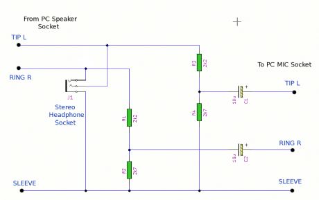
This small and handy device acts as an interface between your computer sound card and is a complete system for listening to streaming audio from the many thousands of Internet Radio Stations. (View)
View full Circuit Diagram | Comments | Reading(767)
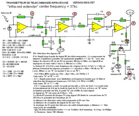
Infra Red Extender Mark 4A 36KHz
Published:2012/11/21 2:13:00 Author:muriel | Keyword: Infra Red, Extender Mark, 4A, 36KHz
An Infra Red wired Repeater circuit to control appliances from a remote location. (View)
View full Circuit Diagram | Comments | Reading(771)
PC Output Interface
Published:2012/11/21 2:10:00 Author:muriel | Keyword: PC , Output Interface
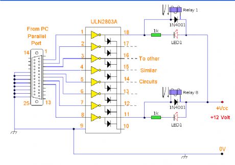
A versaile output interface that can control external devices direct from your computer. Uses freely available software and works with both windows and Linux. (View)
View full Circuit Diagram | Comments | Reading(823)
Infra Red Extender
Published:2012/11/21 2:09:00 Author:muriel | Keyword: Infra Red, Extender
View full Circuit Diagram | Comments | Reading(655)
A Passive Ethernet Hub
Published:2012/11/21 2:08:00 Author:muriel | Keyword: Passive Ethernet Hub
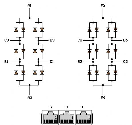
I tested this concept on a little network consisting of three PCs running under Windows 2000. It works well. The network adapters are normal Intel and 3Com models, set to 10 Mbps and Half Duplex. The computers are labelled A, B, C, and the UTP cables from the computers to the hub are 10, 16 and 35 meters long, respectively. (View)
View full Circuit Diagram | Comments | Reading(1873)
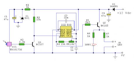
Infra Red Link
Published:2012/11/21 2:04:00 Author:muriel | Keyword: Infra Red, Link
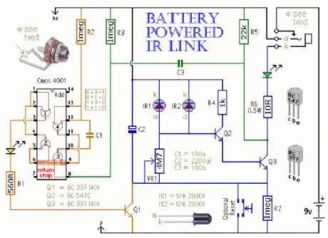
This is a battery powered IR Link which may be used in more than one room. The standby current is extremely low - giving a good battery life; and by shutting down in the presence of extraneous IR radiation it copes with the problem of excessive output current. (View)
View full Circuit Diagram | Comments | Reading(949)
| Pages:65/471 At 206162636465666768697071727374757677787980Under 20 |
Circuit Categories
power supply circuit
Amplifier Circuit
Basic Circuit
LED and Light Circuit
Sensor Circuit
Signal Processing
Electrical Equipment Circuit
Control Circuit
Remote Control Circuit
A/D-D/A Converter Circuit
Audio Circuit
Measuring and Test Circuit
Communication Circuit
Computer-Related Circuit
555 Circuit
Automotive Circuit
Repairing Circuit