
Basic Circuit
Index 69
The magnetic-sticker automatic speech billboard
Published:2012/10/24 22:36:00 Author:Ecco | Keyword: magnetic-sticker, automatic speech, billboard
The automated automatic speech billboard is a magnetic automated voice ad playback device, and its decorative appearance is designed as a welcome cartoon which can be pasted in the lead black pole or advertising signs. When customer approached, it works automatically with welcomed arm swing and playing prerecorded slogan.
(View)
View full Circuit Diagram | Comments | Reading(5524)
The series inductance trimming tap speed adjusting circuit
Published:2012/10/24 22:52:00 Author:Ecco | Keyword: series , inductance , trimming, tap , speed adjusting
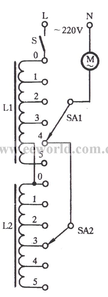
General ceiling fans is turned to fifth block ( end block ), but the speed is still faster with stronger wind. As shown in figure, the governor L1 is connected to a governor L2 in series to increase trimmable buck tap, then the fan can operate with breeze. L1 4 block tap wiring connections disconnect, then the connection is connected as shown in the figure. In this way, the first three gears can be adjusted by L1 governor; When Ll transferred to 4 gear, then SA2 is transferred to an appropriate gear, you can get the breeze.
(View)
View full Circuit Diagram | Comments | Reading(621)
Controlling a relay with a digital logic level.
Published:2012/10/24 1:09:00 Author:muriel | Keyword: relay, digital logic level
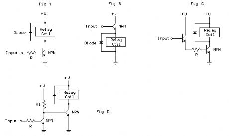
View full Circuit Diagram | Comments | Reading(740)
Ignition Coil Buzz Box
Published:2012/10/24 1:06:00 Author:muriel | Keyword: Ignition Coil , Buzz Box
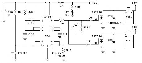
Here's a circuit to create a buzzcoil using a standard automotive ignition coil. A 556 dual timer is used to establish the frequency and duty cycle of the coil current. One of the timers is used as an oscillator to generate the 200 Hz rectangular waveform needed to control the (IRF740 MOSFET) while the second timer switches the oscillator on and off as the breaker points open and close (closed = on). The result is a steady stream of sparks from the ignition coil spaced about 5 milliseconds apart while the breaker points are closed.
Operation:
Pin 8 and 12 are the threshold and trigger inputs of one timer which are driven by the breaker points and produce an inverted signal at the timer output (pin 9). When the points are closed to ground, pin 9 will be high and visa versa. The signal at pin 9 controls the reset line (pin 4) of the second timer and holds the output at pin 5 low while pin 4 is low and pins 8 and 12 are high (points open). The 15K and 4.7K resistors and 0.33uF capacitor are the timing components that establish the frequecy and duty cycle of the second timer which is about 4 milliseconds for the positive interval and 2 milliseconds for the negative. During the positive time interval, the MOSFET gates are held high which causes the ignition coil current to rise to about 4 amps. This equates to about 80 millijoules of energy in the coil which is released into the spark plug when the timer output (pin 5) moves to ground, turning off the MOSFET. A 12 volt zener diode is placed at the junction of the 10 and 27 ohm resistors to insure the MOSFET gate input never goes above 12 volts or lower than -0.7 volts. A 200 volt/5 watt zener is used at the MOSFET drain to limit the voltage to +200 and lengthen the spark duration. The circuit should operate reliably with a shorted plug, however operating the circuit with no load connected (plug wires fallen off, etc.) may cause a failure due to most of the power being absorbed by the zener. You can also use a transient voltage suppressor (TVS) such as the 1.5KE200A or 1.5KE300A in place of the zener. It's probably a better part, but hard to obtain. (View)
View full Circuit Diagram | Comments | Reading(1113)
LM317T Voltage Regulator with Pass Transistor
Published:2012/10/23 22:00:00 Author:muriel | Keyword: LM317T , Voltage Regulator, Pass Transistor
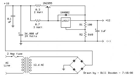
The LM317T output current can be increased by using an additional power transistor to share a portion of the total current. The amount of current sharing is established with a resistor placed in series with the 317 input and a resistor placed in series with the emitter of the pass transistor. In the figure below, the pass transistor will start conducting when the LM317 current reaches about 1 amp, due to the voltage drop across the 0.7 ohm resistor. Current limiting occurs at about 2 amps for the LM317 which will drop about 1.4 volts across the 0.7 ohm resistor and produce a 700 millivolt drop across the 0.3 ohm emitter resistor. Thus the total current is limited to about 2+ (.7/.3) = 4.3 amps. The input voltage will need to be about 5.5 volts greater than the output at full load and heat dissipation at full load would be about 23 watts, so a fairly large heat sink may be needed for both the regulator and pass transistor. The filter capacitor size can be approximated from C=IT/E where I is the current, T is the half cycle time (8.33 mS at 60 Hertz), and E is the fall in voltage that will occur during one half cycle. To keep the ripple voltage below 1 volt at 4.3 amps, a 36,000 uF or greater filter capacitor is needed. The power transformer should be large enough so that the peak input voltage to the regulator remains 5.5 volts above the output at full load, or 17.5 volts for a 12 volt output. This allows for a 3 volt drop across the regulator, plus a 1.5 volt drop across the series resistor (0.7 ohm), and 1 volt of ripple produced by the filter capacitor. A larger filter capacitor will reduce the input requirements, but not much. (View)
View full Circuit Diagram | Comments | Reading(932)
LM317T Variable Voltage Regulator
Published:2012/10/23 21:45:00 Author:muriel | Keyword: LM317T , Variable Voltage, Regulator
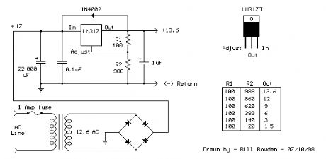
The LM317T is a adjustable 3 terminal positive voltage regulator capable of supplying in excess of 1.5 amps over an output range of 1.25 to 37 volts. The device also has built in current limiting and thermal shutdown which makes it essentially blow-out proof.
Output voltage is set by two resistors R1 and R2 connected as shown below. The voltage across R1 is a constant 1.25 volts and the adjustment terminal current is less than 100uA. The output voltage can be closely approximated from Vout=1.25 * (1+(R2/R1)) which ignores the adjustment terminal current ``but will be close if the current through R1 and R2 is many times greater. A minimum load of about 10mA is required, so the value for R1 can be selected to drop 1.25 volts at 10mA or 120 ohms. Something less than 120 ohms can be used to insure the minimum current is greater than 10mA. The example below shows a LM317 used as 13.6 volt regulator. The 988 ohm resistor for R2 can be obtained with a standard 910 and 75 ohm in series.
When power is shut off to the regulator the output voltage should fall faster than the input. In case it doesn't, a diode can be connected across the input/output terminals to protect the regulator from possible reverse voltages. A 1uF tantalum or 25uF electrolytic capacitor across the output improves transient response and a small 0.1uF tantalum capacitor is recommended across the input if the regulator is located an appreciable distance from the power supply filter. The power transformer should be large enough so that the regulator input voltage remains 3 volts above the output at full load, or 16.6 volts for a 13.6 volt output. (View)
View full Circuit Diagram | Comments | Reading(1101)
Bistable Flip Flop
Published:2012/10/22 22:09:00 Author:muriel | Keyword: Bistable, Flip Flop

Here are two examples of bistable flip flops which can be toggled between states with a single push button. When the button is pressed, the capacitor connected to the base of the conducting transistor will charge to a slightly higher voltage. When the button is released, the same capacitor will discharge back to the previous voltage causing the transistor to turn off. The rising voltage at the collector of the transistor that is turning off causes the opposite transistor to turn on and the circuit remains in a stable state until the next time the button is pressed and released. Note that in the LED circuit, the base current from the conducting transistor flows through the LED that should be off, causing it to illuminate dimly. The base current is around 1 mA and adding a 1K resistor in parallel with the LED will reduce the voltage to about 1 volt which should be low enough to ensure the LED turns completely off.
(View)
View full Circuit Diagram | Comments | Reading(971)
Set/Reset Flip Flop
Published:2012/10/22 22:08:00 Author:muriel | Keyword: Set/Reset, Flip Flop

This is an example of a set/reset flip flop using discrete components. When power is applied, only one of the transistors will conduct causing the other to remain off. The conducting transistor can be turned off by grounding it's base through the push button which causes the collector voltage to rise and turn on the opposite transistor. (View)
View full Circuit Diagram | Comments | Reading(1253)
Experiments with Detector Diodes
Published:2012/10/22 22:07:00 Author:muriel | Keyword: Experiments, Detector Diodes

When building crystal radios or other simple receivers, the experimenter often wonders about the relative performance of the different diodes in the junk box. Here are the results of several experiments using the typical types available to the hobbyist. The source is a low impedance and the load is a fairly high impedance. A particular diode will behave differently with different impedance levels but for low received signal levels these measurements are fairly predictive of the relative performance in most circuits. The diode types include germanium, silicon, Schottky, and even a light-emitting diode! The test setup uses an accurate RF synthesizer, a homemade AM pin diode modulator driven by an audio generator, a simple test fixture, a DC power supply for adding bias current, and a sensitive audio voltmeter. The setup shown below was used to test the diodes at several frequencies with a low modulation index (about 20%) and the near optimum bias current was determined by varying the DC supply. (View)
View full Circuit Diagram | Comments | Reading(988)
Inductive proximity switch circuit
Published:2012/10/21 20:30:00 Author:Ecco | Keyword: Inductive, proximity switch

The circuit includes a sinusoidal oscillator (T1), switching amplifier (T2) and relay (Im = 50mA). If metal plunger is inserted into the coils, the inductance feedback will make the oscillator oscillation stop, the switching amplifier is turned off, then the relay releases. The switch point push depth tolerance is approximately ± 2mm.
(View)
View full Circuit Diagram | Comments | Reading(3962)
Frequency selective photoelectric relay circuit
Published:2012/10/21 22:51:00 Author:Ecco | Keyword: Frequency selective , photoelectric relay

The circuit can use modulated optical signal to control the relay. The modulation frequency is approximately 2.7kHz, and the selectivity of receiving circuit is determined by two parallel T-network. The parameters of RC elements decide narrow stopband with 2.7kHz center. Figure a shows controlling the circuit for transmitter portion of the circuit, and it uses a GaAs light emitting diode CQY12B, and two transistors constitute a multivibrator with 2.7kHz resonant frequency, and it outputs the rectangular wave pulse. It uses 250Ω potentiometer to accurately tune frequency.
(View)
View full Circuit Diagram | Comments | Reading(1045)
Voltage Regulator (13.6 volts)
Published:2012/10/22 1:23:00 Author:muriel | Keyword: Voltage Regulator, 13.6 volts

View full Circuit Diagram | Comments | Reading(640)
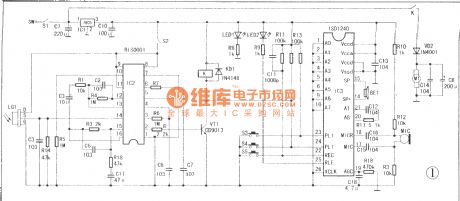
The voice recorder module hardware circuit
Published:2012/10/19 1:01:00 Author:Ecco | Keyword: voice recorder , module hardware

MK1 is a microphone for recording voice, and it can complete an ordinary live recording. In playback circuit, the output selects low voltage general purpose integrated power amplifier LM386M-1's typical application circuit as speaker LS1's driver circuit. In typical circuit, a 10μF bypass capacitor is connected between LM386M - 1's 1 feet and 8 feet to increase magnification with 200 times.
(View)
View full Circuit Diagram | Comments | Reading(1503)
Astable Multivibrator
Published:2012/10/19 0:53:00 Author:muriel | Keyword: Astable Multivibrator

View full Circuit Diagram | Comments | Reading(0)
32.768 KHz oscillator using a watch crystal
Published:2012/10/18 22:56:00 Author:muriel | Keyword: 32.768 KHz , oscillator, watch crystal

Below are a couple circuits you can use to produce a 32.768 KHz square wave from a common watch crystal. The output can be fed to a 15 stage binary counter to obtain a 1 second square wave. The circuit on the left using the 4069 inverter is recommended over the transistor circuit and produces a better waveform. The single transistor circuit produces more of a ramping waveform but the output swings the full supply voltage range so it will easily drive the input to a CMOS binary counter. (View)
View full Circuit Diagram | Comments | Reading(1733)
Single Op-Amp Bandpass Filter
Published:2012/10/18 3:44:00 Author:muriel | Keyword: Single, Op-Amp , Bandpass Filter

A bandpass filter passes a range of frequencies while rejecting frequencies outside the upper and lower limits of the passband. The range of frequencies to be passed is called the passband and extends from a point below the center frequency to a point above the center frequency where the output voltage falls about 70% of the output voltage at the center frequency. These two points are not equally spaced above and below the center frequency but will look equally spaced if plotted on a log graph. The percentage change from the lower point to the center will be the same as from the center to the upper, but not the absolute amount. This is similar to a musical keyboard where each key is separated from the next by the same percentage change in frequency, but not the absolute amount.
The filter bandwidth (BW) is the difference between the upper and lower passband frequencies. A formula relating the upper, lower, and center frequencies of the passband is:
Center Frequency = Square Root of (Lower Frequency * Upper Frequency)
The quality factor, or Q of the filter is a measure of the distance between the upper and lower frequency points and is defined as (Center Frequency / BW) so that as the passband gets narrower around the same center frequency, the Q factor becomes higher. The quality factor represents the sharpness of the filter, or rate that the amplitude falls as the input frequency moves away from the center frequency during the first octave. As the frequency gets more than one octave away from center frequency the rollof approaches 6 dB per octave regardless of Q value. Approximate rolloff rates for different Q values for a single octave change from center frequency are:
Q = 1 = 6 dB Q = 5 = 18 dB Q = 10 = 24 dB Q = 50 = 40 dB
For a single op-amp bandpass filter with both capacitors the same value, the Q factor must be greater than the square root of half the gain, so that a gain of 98 would require a Q factor of 7 or more.
The example below shows a 1700 Hz bandpass filter with a Q of 8 and a gain of 65 at center frequency (1700 Hz). Resistor values for the filter can be worked out using the three formulas below. Both capacitor values need to be the same for the formulas to work and are chosen to be 0.01uF which is a common value usable at audio frequencies. This same filter is used in the Whistle On / Whistle Off relay toggle circuit.
R1 = Q / (G*C*2*Pi*F) = 8/(65 * .00000001 * 6.28 * 1700) = 1152 or 1.1K R2 = Q / ((2*Q^2)-G)*C*2*Pi*F) = 8/((128-65) * .00000001 * 6.28 * 1700) = 1189 or 1.2K R3 = (2*Q) / (C*2*Pi*F) = 16 / (.00000001 * 6.28 * 1700) = 150K (View)
View full Circuit Diagram | Comments | Reading(2009)
3 lines mixer
Published:2012/10/18 2:25:00 Author:muriel | Keyword: 3 lines, mixer

This project is a 3 or more lines mixer. For more than 3 inputs you can repeat the input parts (P=10K R=22K). It powered with 9Vdc.
(View)
View full Circuit Diagram | Comments | Reading(747)
The LM317T application circuit diagram
Published:2012/10/17 21:53:00 Author:Ecco | Keyword: application

It uses LM317T to make adjustable power supply, but the problem is that the load is often burned due to poor contact of potentiometer and output voltage increases. If the circuit increases a transistor, under normal circumstances, the base potential of T1 is 0, and T1 is cut off, and it has no effect on the circuit; when W1 is in poor contact, the base of T1 electrode potential rises, when it is raised to 0.7V, T1 gets conduction to reduce LM317T adjustment terminal voltage, then the output voltage is also reduced, thereby to play a protective role on the load.
(View)
View full Circuit Diagram | Comments | Reading(5246)
Knife switch start circuit
Published:2012/10/16 22:08:00 Author:Ecco | Keyword: Knife switch start

The knife switch inlcudes plastic cover porcelain bottom knife switch, Hulled knife switch and flagstone knife switch. It can directly start small motor with power being less than 7.5kW, the circuit is shown in the figure. The switch is matched with fuse pipe or wiring connected to fuse pile, so it is very convenient to replace fuse. Operation methods: you can close the knife switch, the motor M rotates; if you pull the knife switch motor, M will stop. The circuit can be widely used in pumps, rice mill, grinding machines and other small machinery.
(View)
View full Circuit Diagram | Comments | Reading(1088)
Jog combined with long-running start-up circuit
Published:2012/10/16 22:20:00 Author:Ecco | Keyword: Jog , long-running start-up

In reality, sometimes it needs to manually jog to operate the motor for long operation. The circuit shown in Figure is designed to address this issue. When the start button ST is pressed, motor M is normal startup, and the circuit utilizes its normally open auxiliary contact to lock it by itself, then the motor M can make long-term operation. Pressing STP can stop motor M. If you press the button SB, motor M starts. Because pressing SB normally open contact also disconnects normally closed contacts, and SB is loosen, KM loses electric, then motor M stops, this mode is called jog .
(View)
View full Circuit Diagram | Comments | Reading(1343)
| Pages:69/471 At 206162636465666768697071727374757677787980Under 20 |
Circuit Categories
power supply circuit
Amplifier Circuit
Basic Circuit
LED and Light Circuit
Sensor Circuit
Signal Processing
Electrical Equipment Circuit
Control Circuit
Remote Control Circuit
A/D-D/A Converter Circuit
Audio Circuit
Measuring and Test Circuit
Communication Circuit
Computer-Related Circuit
555 Circuit
Automotive Circuit
Repairing Circuit