
Basic Circuit
Index 75
Four-stage telecom filter circuit with 1KHZ frequency
Published:2012/9/13 22:43:00 Author:Ecco | Keyword: Four-stage , telecom, filter , 1KHZ frequency

Third-order asymmetric filter circuit has two ways of output UA1 and UA2, the former is high-pass filter output, and the later is low-pass filter output.
(View)
View full Circuit Diagram | Comments | Reading(1249)
Third-order asymmetric filter circuit
Published:2012/9/17 1:34:00 Author:Ecco | Keyword: Third-order , asymmetric, filter

In the figure, thethird-order asymmetric filter has two ways of output UA1 and UA2, the former is high-pass filter output, and the later is the low-pass filter output.
(View)
View full Circuit Diagram | Comments | Reading(837)
Single-phase full-wave rectifier Π filter circuit
Published:2012/9/13 22:39:00 Author:Ecco | Keyword: Single-phase, full-wave, rectifier, Π filter

Typically, under the case with low current of the rectifier circuit (several tens mA ) , it may use resistor R with appropriate power, and can reduce the weight of the filter to reduce costs. The circuit is shown in the diagram.
(View)
View full Circuit Diagram | Comments | Reading(1777)
Auto - primary and secondary windings different voltage buck governor circuit
Published:2012/9/14 1:58:00 Author:Ecco | Keyword: Auto - primary , secondary windings , different voltage buck , governor
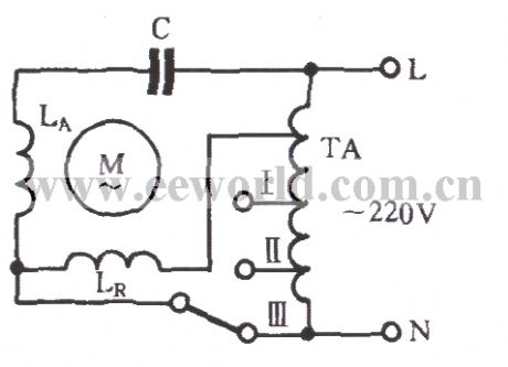
As shown in the diagram, the autotransformer TA is applied to the main and auxiliary winding LR to LA with different voltages for Buck governor. It uses autotransformer TA Buck governor to improve the motor start-up performance and power consumption. The disadvantage is that the autotransformer increases the whole volume and cost.
(View)
View full Circuit Diagram | Comments | Reading(563)
DC separately excited motor commutation circuit
Published:2012/9/13 22:34:00 Author:Ecco | Keyword: DC separately excited , motor , commutation
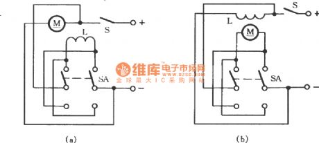
Therotation direction of the DC motor is determined by the direction of current in the field and windings, the field direction of the magnetic field is determined by the direction of excitation windingcurrent. In the diagram (a), switching switch SA can change the positive and negative electrode connection of excitation coil (winding) L, while the polarity of the power keeps constant, it can change the rotation direction of the motor. In the diagram (b), it can use SA to change the polarity of power's two ends, and the polarity of the magnetic coil keeps constant, and it can also achieve reversible steering. If the polarity of the excitation coil and the power is changed at the same time, the direction of generated magnetic field will not change, so the direction of rotation will maintain.
(View)
View full Circuit Diagram | Comments | Reading(1018)
Change-over switch selecting operating mode circuit
Published:2012/9/14 1:41:00 Author:Ecco | Keyword: Change-over switch , selecting , operating mode

As shown in the figure, S is a changeover switch. When it is turned off, pressing the start button ST can only do inching control; When S is closed, the KM's normally closed contacts are switched on, so pressing the ST can make KM achieve self-locking, the motor can make long-term operation.
(View)
View full Circuit Diagram | Comments | Reading(3100)
Fuse indicator circuit with discoloring light-emitting diode
Published:2012/9/14 2:49:00 Author:Ecco | Keyword: Fuse indicator, discoloring light-emitting diode
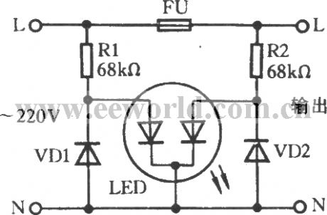
As shown in the figure, it is the fuse indicator circuit for single-phase AC circuit. LED is a discoloring light-emitting diode in the figure. When fuse FU is normal, the two light-emitting diodes in LED emit orange light; Once the fuse inside of the fuse is blown, the right light-emitting diode doesn't emit light without power, only the left one still emit red light.
(View)
View full Circuit Diagram | Comments | Reading(1968)
Automatically motor start circuit with RD9481 Doppler effect sensor
Published:2012/9/16 22:56:00 Author:Ecco | Keyword: Automatically motor start , Doppler effect sensor
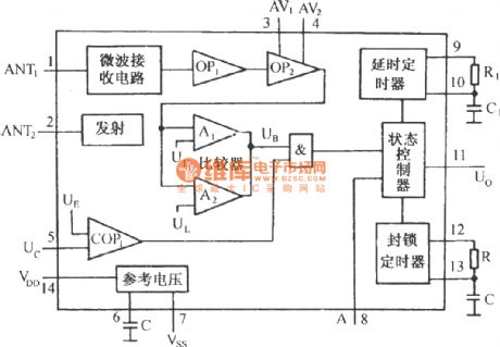
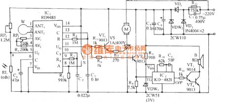
The circuit is shown as the figure. It includes the Doppler effect sensor control circuit, thyristor control circuit, music sound circuit, amplifier circuit and AC buck rectifier circuit. Doppler effect sensor integrated circuit RD9481 is the core device of the circuit, and its internal functional block diagram is shown in the following figure.
(View)
View full Circuit Diagram | Comments | Reading(2171)
0 to 9 asynchronous decade counter 7490 display
Published:2012/9/16 21:56:00 Author:Ecco | Keyword: 0 to 9 , asynchronous decade counter , display
The circuit is based on asynchronous decade counter 7490(IC2), a 7 segment display (D1), and a seven segment decoder/driver IC 7446 (IC1).The seven segment display consists of 7 LEDs labelled a through g. By forward biasing different LEDs, we can display the digits 0 through 9. (View)
View full Circuit Diagram | Comments | Reading(780)
ENERGY RECYCLING CIRCUIT
Published:2012/9/16 21:54:00 Author:Ecco | Keyword: ENERGY RECYCLING
so what happens when you flip a switch? When you try to stop the flow of current in 'zero' time its equivalent to trying to stop a freight train instantaneously. you get a huge voltage buildup dv/dt = X/0=infinity This is one example of the use of a relativistic property of electricity. We may not be able to stop freighttrains instantaneously, but we can come close with electron trains. (View)
View full Circuit Diagram | Comments | Reading(702)
Free Energy Schematic
Published:2012/9/16 21:53:00 Author:Ecco | Keyword: Free Energy

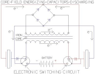
The basic concept as I understand it, is a high frequency high voltage low current rectified and then used to charge a bank of high value capacitors and then to discharge them in pulse mode for brief period of time, nano seconds in fact by, means of a high speed electronic switching circuit or mechanical device and a rectification method that will only allow the high voltage charge to flow in one direction. (View)
View full Circuit Diagram | Comments | Reading(3048)
Bedini SG Energiser
Published:2012/9/16 21:53:00 Author:Ecco | Keyword: Bedini SG Energiser

John Bedini has been working in what is sometimes known as the free energy field for 35 years now. He would be amongst the first to correct this description as he would describe himself as involved with Free Radiant Energy which is not the same thing i.e. he is harnessing a form of energy little understood by the most of us. (View)
View full Circuit Diagram | Comments | Reading(4128)
Swiss ML Testakica
Published:2012/9/16 21:52:00 Author:Ecco | Keyword: Swiss , ML Testakica

The Unit is started by hand by revolving the two disks in opposite directions and continues to move without further input. This device has only two moving parts namely the bearing races at the centre of the disk. The disk are made of clear plastic upon which are placed flat a series of fifty blade type steel or aluminium sections equally spaced around the middle sections of each disk. The speed of the revolving disks is about 50 to 60 rpm limited to this by magnetic impulses from the magnetic section on the rim. (View)
View full Circuit Diagram | Comments | Reading(966)
Tesla's Energy Reciever
Published:2012/9/16 21:52:00 Author:Ecco | Keyword: Tesla, Energy Reciever

Tesla's free-energy receiver was patented in 1901 as An Apparatus for the Utilization of Radiant Energy. The patent refers to the Sun, as well as other sources of radiant energy, like cosmic rays. That the device works at night is explained in terms of the night-time availability of cosmic rays. Tesla also refers to the ground as a vast reservoir of negative electricity. . (View)
View full Circuit Diagram | Comments | Reading(1355)
Bedini Circuit
Published:2012/9/16 21:51:00 Author:Ecco | Keyword: Bedini

The power is all in the timed switching process. There are two main principles I use of switching the radiant energy the John Bedini way. First, the SG/SSG, Icehouse unidirectional circuit or John Bedini Monopole with the School Girl Circuit (SG) Mechanical-Oscillator-Energizer and second, the John Bedini/Ron Cole switching oscillator circuit. Since my SSG4a/SG4a is a John Bedini/Ron Cole switching oscillator circuit, I should have called it BC4a meaning Bedini/Cole4a. (just to get the facts straight :) The main difference is the transistor arrangement of the first, usually in parallel, meaning for every wire a transistor/multiplying the J. Bedini circuit on the same heat-sink, which is used mainly for charging batteries and driving the rotor. (View)
View full Circuit Diagram | Comments | Reading(2506)
Free heater circuit by Rosemary Ainslie
Published:2012/9/16 21:51:00 Author:Ecco | Keyword: Free heater, Rosemary Ainslie

Rosemary's original test circuit is shown in the article she tried to have published in a refereed scientific journal, but the submission was always rejected. In the last 5 months, I have had extensive email correspondence, and numerous telephone conversations with Rosemary, who lives in South Africa. After studying her work, I was absolutely thrilled with her discovery of the super-efficient heating effect. In mid-February of this year, I proposed to her an idealized schematic of her DC resonance circuit to produce the effects she had discovered. (View)
View full Circuit Diagram | Comments | Reading(8396)
Hans Coler Passive Circuit
Published:2012/9/16 21:49:00 Author:Ecco | Keyword: Hans Coler Passive

He called this device the Stromerzeuger and for a few watts from a dry battery it provided 6 kW continuously. He was refused development support because it was a perpetual motion machine. Hans also invented a passive device which he called the Magnetstromapparat. His unit required very careful and slow adjustment to get it operating but when it started it continued on test in a locked room for three months of continuous operation. (View)
View full Circuit Diagram | Comments | Reading(1458)
Utilisation of Radiant Energy
Published:2012/9/16 21:47:00 Author:Ecco | Keyword: Utilisation , Radiant Energy

This was filed on 21 March 1901 and granted on 5 November 1901. It was entitled: 'Apparatus for the Utilisation of Radiant Energy'. By installing two metal plates, one high above the ground and the other at ground level, with wires connecting the plates to separate electrodes of a capacitor, it was stated that the capacitor became charged to a very high potential, the energy input being that radiated to Earth from outer space. This may well have motivated the efforts of T. Henry Moray but, so far as this Applicant's invention is concerned, no such input from overhead components is necessary as a quite different energy source is at work, namely the zero-point vacuum energy activity of our quantum. (View)
View full Circuit Diagram | Comments | Reading(1155)
Electret Circuit
Published:2012/9/16 21:47:00 Author:Ecco | Keyword: Electret

Arcing completes a circuit -- closes a system -- between two voltage potentials. When arcing occurs, two oppositely charged static voltage potentials can cancel each other out. The arcing problems that occur are usually between two electrically isolated voltage potentials pressures necessary to hold a charge and they are part of the same circuit -- completes a closed system. (View)
View full Circuit Diagram | Comments | Reading(784)
Solid State Free energy Circuit
Published:2012/9/16 21:47:00 Author:Ecco | Keyword: Solid State, Free energy

It's very simple actually. The idea is that we use what we have learned from the capacitor tests to create a circuit that uses the capacitors to run the load and then by discharging the 1/2 full capacitor into a DC-DC converter we can recharge the initial cap and start again. And have some energy left over. (View)
View full Circuit Diagram | Comments | Reading(4411)
| Pages:75/471 At 206162636465666768697071727374757677787980Under 20 |
Circuit Categories
power supply circuit
Amplifier Circuit
Basic Circuit
LED and Light Circuit
Sensor Circuit
Signal Processing
Electrical Equipment Circuit
Control Circuit
Remote Control Circuit
A/D-D/A Converter Circuit
Audio Circuit
Measuring and Test Circuit
Communication Circuit
Computer-Related Circuit
555 Circuit
Automotive Circuit
Repairing Circuit