
Basic Circuit
Index 62
Exclusive-OR gates 3
Published:2012/12/27 0:55:00 Author:muriel | Keyword: Exclusive-OR gates

View full Circuit Diagram | Comments | Reading(709)
Exclusive-OR gates 2
Published:2012/12/27 0:55:00 Author:muriel | Keyword: Exclusive-OR gates

View full Circuit Diagram | Comments | Reading(596)
Exclusive-OR gates
Published:2012/12/27 0:54:00 Author:muriel | Keyword: Exclusive-OR gates

View full Circuit Diagram | Comments | Reading(0)
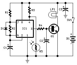
Nocturnal Animals Whisker
Published:2012/12/24 21:29:00 Author:muriel | Keyword: Nocturnal Animals Whisker
View full Circuit Diagram | Comments | Reading(941)
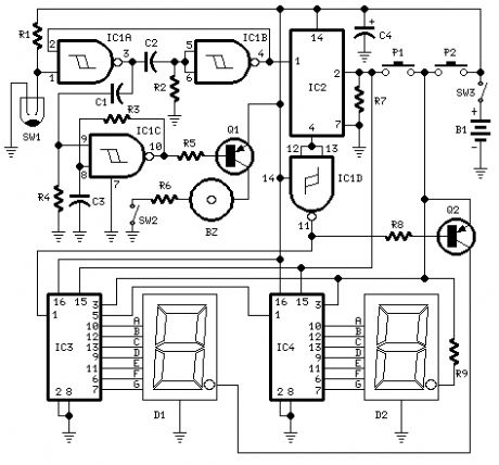
Digital Step-Km Counter
Published:2012/12/21 21:39:00 Author:muriel | Keyword: Digital Step-Km Counter
View full Circuit Diagram | Comments | Reading(946)
The R3 trigger circuit with adjustable trigger level
Published:2012/12/21 1:18:00 Author:Ecco | Keyword: R3 trigger , adjustable trigger level

The circuit has two input terminals, i.e. the triggered terminal ( pin 8 ) and reset terminal ( pin 12 ). The trigger level is adjusted by potentiometer RP (10kΩ). Figure b illustrates the pulse waveform. At time t1, the input voltage UE = U8 is lower than the setting trigger voltage U6 = U7, and the reset input remains high ( + U.S. ) level, the pin 14 outputs high level to block the output terminal (pin 2), then U2 is in low level. Until UE = U8 achieve the setting trigger voltage U6 = U7, output voltage U2 only changes to high from low level.
(View)
View full Circuit Diagram | Comments | Reading(604)
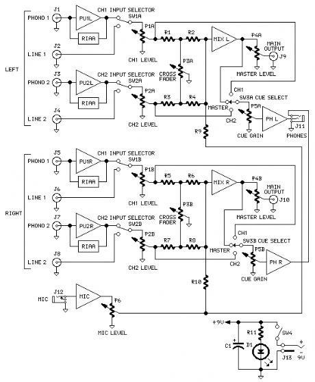
General Circuit diagram
Published:2012/12/20 21:08:00 Author:muriel | Keyword: General Circuit diagram
View full Circuit Diagram | Comments | Reading(821)
Bass and treble tone two-way control circuit diagram
Published:2012/12/20 2:19:00 Author:Ecco | Keyword: Bass , treble tone, two-way control

Bass and treble circuits are connected together to constitute two-way control tone control circuit shown in figure.
(View)
View full Circuit Diagram | Comments | Reading(1912)
Audio automatically compressed circuit diagram
Published:2012/12/20 2:37:00 Author:Ecco | Keyword: Audio, automatically compressed

This simple automatic audio compression circuit uses direct regulation technology to control amplitude of the output signal. In contrast, the common feedback technique is used to adjust the input signal. In many audio applications, it's important to have a constant level for the audio signal. This is a real circuit specifically for speech modulated radio transmission applications. The speech circuit is also often applied to the intercom or telephone system. This the sound adjustment cost price is not very expensive. The circuit design here uses simple and inexpensive material.
(View)
View full Circuit Diagram | Comments | Reading(973)
4 ~ 20mA temperature transmitter circuit using voltage output integrated temperature sensor
Published:2012/12/20 2:11:00 Author:Ecco | Keyword: 4 ~ 20mA, temperature transmitter , voltage output, integrated temperature sensor

The circuit can convert TMP35 output voltage signal into a standard 4 ~ 20mA current signal for the Automation Instrumentation and industrial temperature control. It uses 4mA as zero-scale value, 20mA as full scale value. REF193 is the 3V reference voltage source, OP193 is an op amp. RP1, RP2 are respectively calibrate full scale and zero potentiometers, the two can be adjusted independently by each other. The VD1 is an Schottky diode, it can prevent the rising of OP193 open loop voltage. The Supply Voltage is available in the range of +9 ~ +18 V.
(View)
View full Circuit Diagram | Comments | Reading(3246)
Basic connection diagram of INA326/327 signal and power
Published:2012/12/18 1:38:00 Author:Ecco | Keyword: Basic connection, signal , power
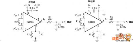
It selects most accurate 0.1μF capacitor for the power supply filtering, and it should be placed as close as possible to the chip power pin. Ro, Co are an output filters which can filter the output noise of circuit; at the same time, it can be used as the input filter for next-stage circuit, such as an input filter of analog - digital converter. The output voltage is based on the ground terminal of R2 / / C2 basis.
(View)
View full Circuit Diagram | Comments | Reading(1087)
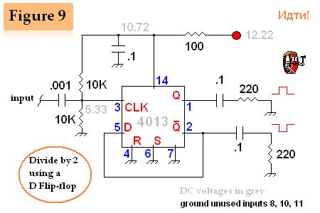
D Flip-Flop with dual or single output.
Published:2012/12/17 20:37:00 Author:muriel | Keyword: D Flip-Flop, dual or single output.
View full Circuit Diagram | Comments | Reading(1135)
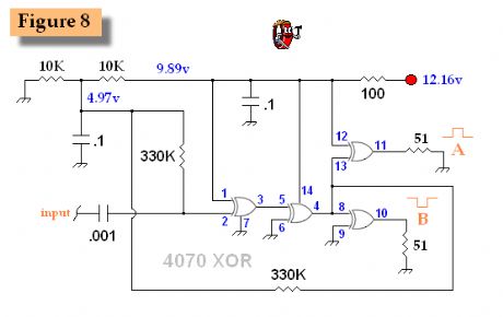
"popcorn" XOR output balancer
Published:2012/12/17 20:36:00 Author:muriel | Keyword: "popcorn" XOR , output balancer
View full Circuit Diagram | Comments | Reading(547)
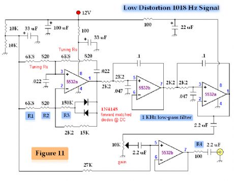
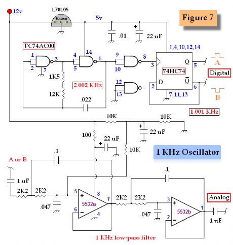
One KHz Low Distortion Signal Generator
Published:2012/12/17 20:28:00 Author:muriel | Keyword: One KHz , Low Distortion , Signal Generator
View full Circuit Diagram | Comments | Reading(1950)
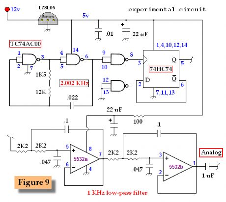
One KHz Digital and Analog Oscillator 2
Published:2012/12/17 20:27:00 Author:muriel | Keyword: One KHz, Digital and Analog , Oscillator
View full Circuit Diagram | Comments | Reading(621)
One KHz Digital and Analog Oscillator
Published:2012/12/17 20:26:00 Author:muriel | Keyword: One KHz, Digital and Analog, Oscillator
View full Circuit Diagram | Comments | Reading(782)
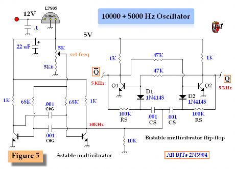
10000 and 5000 Hz Multivibrator Clock
Published:2012/12/17 20:26:00 Author:muriel | Keyword: 10000 and 5000 Hz, Multivibrator Clock
View full Circuit Diagram | Comments | Reading(746)
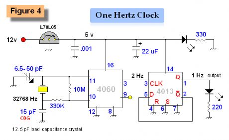
One Hertz Precision Time Base
Published:2012/12/17 20:25:00 Author:muriel | Keyword: One Hertz , Precision Time Base
View full Circuit Diagram | Comments | Reading(1250)
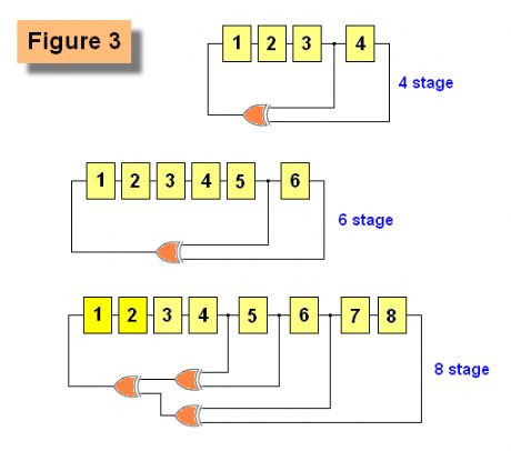
Pseudo-Random Number Generator 3
Published:2012/12/17 20:25:00 Author:muriel | Keyword: Pseudo-Random, Number Generator 2
View full Circuit Diagram | Comments | Reading(1793)
Pseudo-Random Number Generator 2
Published:2012/12/17 20:24:00 Author:muriel | Keyword: Pseudo-Random , Number Generator 2

View full Circuit Diagram | Comments | Reading(1449)
| Pages:62/471 At 206162636465666768697071727374757677787980Under 20 |
Circuit Categories
power supply circuit
Amplifier Circuit
Basic Circuit
LED and Light Circuit
Sensor Circuit
Signal Processing
Electrical Equipment Circuit
Control Circuit
Remote Control Circuit
A/D-D/A Converter Circuit
Audio Circuit
Measuring and Test Circuit
Communication Circuit
Computer-Related Circuit
555 Circuit
Automotive Circuit
Repairing Circuit