About SeekIC | Services | Payment | Advertisements service | Contact Us | Links
© 2008-2012 SeekIC.com Corp.All Rights Reserved.

Published:2012/9/4 20:56:00 Author:Ecco | Keyword: Battery Charge, Current Indicator

This circuit turns on a LED whenever it detects at least 25ma of battery charge current.
Source: discovercircuits (View)
View full Circuit Diagram | Comments | Reading(3553)
Published:2012/9/4 20:55:00 Author:Ecco | Keyword: Acceptable , Voltage Indicator

I have used this circuit many times in custom test fixtures where a simple go-no go indication was needed. The circuit can also be used to adjust a particular voltage be within specific high or low limits. The three LEDs will indicate if the voltage is high, low or OK. When connected to other converters, such as a frequency to voltage converter, a current to voltage converter or a power to voltage meter, it could provide a quick indication of a proper level.
Source: discovercircuits (View)
View full Circuit Diagram | Comments | Reading(936)
Published:2012/9/4 20:54:00 Author:Ecco | Keyword: Low Value, Capacitance Meter

This circuit was originally designed to measure the volume of fluid inside a medical syringe. As designed, it produces a zero to 5 volt output, corresponding to a capacitance change of about 10 picofarads. With a digital voltmeter, at its output, it can resolve a capacitance change of 0.002 picofarads or 2 femtofarads.
Source: discovercircuits (View)
View full Circuit Diagram | Comments | Reading(3435)
Published:2012/9/4 20:53:00 Author:Ecco | Keyword: 5V , CAPACITANCE, TOUCH , ACTIVATED MOMENTARY SWITCH

This circuit is discussed in more detail in the section on Capacitance Proximity Switch Technology. The circuit is powered from a standard +5v supply. It has both a source and sink output that change state whenever a metal button connected to the circuit is touched. An earth ground reference is required.
Source: discovercircuits (View)
View full Circuit Diagram | Comments | Reading(1463)
Published:2012/9/4 20:51:00 Author:Ecco | Keyword: Ultracapacitor , Voltage Limiting

Supercapacitors are working their way into more and more applications where electrical energy needs to be stored. These robust devices can be charged and discharged 1000s of times and will typically outlast a battery. Many supercap manufacturers claim a life span of 10 years or more. A supercapacitor is often chosen to supply power to low current load for many hours at a time, recharged by a solar panel.
Source: discovercircuits (View)
View full Circuit Diagram | Comments | Reading(1318)
Published:2012/9/4 20:46:00 Author:Ecco | Keyword: MACHINE POWER, LOSS BEEPER

For some medical equipment it is important for an operator when power is lost to the machine. The beeper is powered from a 9v battery and requires the machine to have a power switch with a third set of contacts.
Source: discovercircuits (View)
View full Circuit Diagram | Comments | Reading(604)
Published:2012/9/4 20:45:00 Author:Ecco | Keyword: 12V , TOUCH SWITCH, EXCITER CIRCUIT

This circuit is designed to generate a 20KHz pseudo sine wave signal that can power about 50 remote touch activated switch circuits. It can support a cable length of about 2500 feet. A typical remote switch circuit is also shown as well as a receiver circuit for those switches.
Source: discovercircuits (View)
View full Circuit Diagram | Comments | Reading(968)
Published:2012/9/4 20:43:00 Author:Ecco | Keyword: CAPS , PROVIDE VOLTAGE BOOST, SERIES REGULATOR

This circuit adds some capacitors and diodes to a traditional transformer type series regulator circuit to extend the normal operating range. It can insure regulation during low line voltage conditions or it can squeeze a few more watts out of a plug-in-the-wall power adapter power supply.
Source: discovercircuits (View)
View full Circuit Diagram | Comments | Reading(1368)
Published:2012/9/4 20:25:00 Author:Ecco | Keyword: Automotive Electrical , Voltage Indicator

This circuit will indicate if an automotive electrical circuit has zero volts or 12 volts present.
Source: discovercircuits (View)
View full Circuit Diagram | Comments | Reading(1077)
Published:2012/9/4 20:23:00 Author:Ecco | Keyword: Piezoelectric , Vibration, Sensor, Activates , Switch

An inexpensive piezoelectric wafer is used to detect vibration and when the vibration is sufficient a switch is activated.
Source: discovercircuits (View)
View full Circuit Diagram | Comments | Reading(2696)
Published:2012/9/4 20:23:00 Author:Ecco | Keyword: Piezoelectric, Triggered, Switch
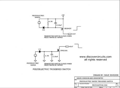
Two different switch circuits are shown. One sources current and the second sinks current. Both switches are connected to a piezoelectric wafer. When the wafer is tapped, the switches are activated.
Source: discovercircuits (View)
View full Circuit Diagram | Comments | Reading(1164)
Published:2012/9/4 20:18:00 Author:Ecco | Keyword: WIDE BAND , ZERO , CROSS , DETECTOR

This circuit was designed to convert a low amplitude 40KHz signal into a clean square wave signal. It will work with inputs as small as 5mv peak-to-peak or as large as 3 volts peak to peak. The input frequency can range from a few kilohertz to about 150KHz.
Source: discovercircuits (View)
View full Circuit Diagram | Comments | Reading(8178)
Published:2012/9/4 20:14:00 Author:Ecco | Keyword: N-CH, P-CH , TRANSISTORS , PUSH-PULL DRIVER
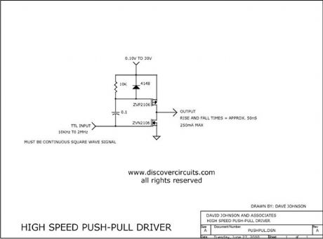
This circuit can produce high speed output signals with fast rise and full times. The unique change pump action allows the voltage of the upper P-ch device to range from millivolts to hundreds of volts. The output current is only limited by the rating of the transistors. I have used this circuit beyond 2MHz.
Source: discovercircuits (View)
View full Circuit Diagram | Comments | Reading(739)
Published:2012/9/4 20:13:00 Author:Ecco | Keyword: CIRCUIT FORMS DIVIDE , 1.5 COUNTER
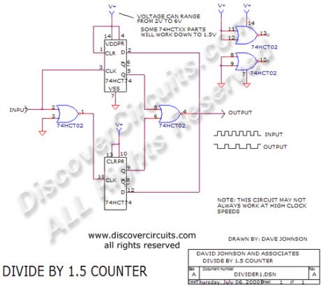
Two inexpensive ICs divide a TTL clock signal by 1.5. By following the circuit with another flip/flop, you could also generate a divide by three function.
Source: discovercircuits (View)
View full Circuit Diagram | Comments | Reading(1603)
Published:2012/9/4 20:10:00 Author:Ecco | Keyword: AUDIO , AMP, + 3KHz , FILTER

This circuit is the audio amp section for a complete optical transmitter. The circuit amplifies and filters the voice audio signals from an electret microphone. The circuit is described in more detail in the receiver section of Dave Johnson's Handbook of Optical Through the Air Communications.
Source: discovercircuits (View)
View full Circuit Diagram | Comments | Reading(3)
Published:2012/9/4 20:09:00 Author:Ecco | Keyword: HIGH PASS , ACTIVE , FILTER COLLECTION
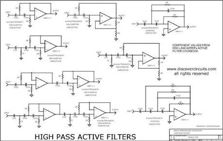
This is a collection of inverting and non-inverting active high pass filter circuits. I included one, two three, four and six pole filter circuits. You can change the component value ratios shown to achieve any frequency cut-off you may need. The circuit does not specify an operational amplifier. The circuits should be used to select the needed resistor and capacitor components for a particular frequency knee and slope.
Source: discovercircuits (View)
View full Circuit Diagram | Comments | Reading(3956)
Published:2012/9/4 20:07:00 Author:Ecco | Keyword: Energy Harvesting , Current Transformer
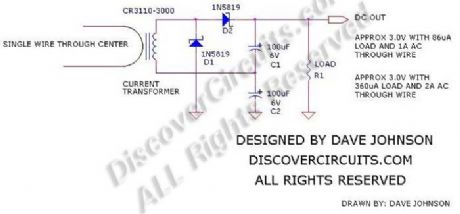
Energy harvesting is all the rage these days. With some modern electronics, information from low power sensors can be sent to a distant data collection point using a low power RF transmitter. To power these remote sensors, various energy sources can be tapped into. Machine vibration, temperature differences, ambient light and stray RF have all been used as low power energy sources. Sometimes, the sensors are located near AC power cables. Rather than making a direct connection to those cables, an AC current transformer, such as the one shown below, can be used to capture a bit of power.
Source: discovercircuits (View)
View full Circuit Diagram | Comments | Reading(1604)
Published:2012/9/4 3:59:00 Author:Ecco | Keyword: ISOLATED , AC , CURRENT , MONITOR
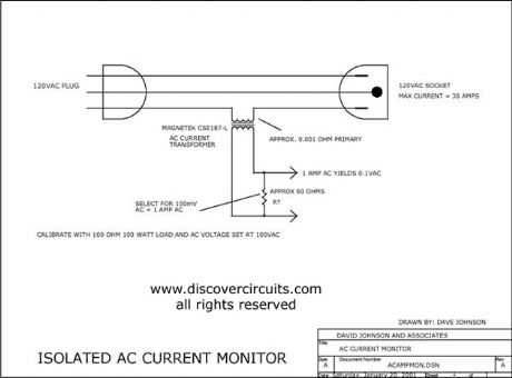
This circuit uses a small AC current transformer from Magnetek to produce an isolated voltage proportional to the AC current in the primary winding. The transformer contains a single turn primary with a low 0.001-ohm resistance. It can easily handle 30 amps of AC current and provides at least 500vac of isolation. With the components shown, the output AC voltage is scaled so 1 amp of current produces 100mv of AC voltage.
Source: discovercircuits (View)
View full Circuit Diagram | Comments | Reading(1999)
Published:2012/9/3 22:26:00 Author:Ecco | Keyword: Dual-channel, radio , remote control , light switch

As shown in the figure, it is a dual-channel radio remote control light switch circuit with dedicated radio transmitter and receiver modules, and it can independently control the on-off of two lamps, and the circuit structure is very simple.
Figure b shows the key chain emitter.
(View)
View full Circuit Diagram | Comments | Reading(3390)
Published:2012/9/3 21:45:00 Author:Ecco | Keyword: Double-control, lamp switch

Dual - control switch is also known as the double switch, it is generally installed in two different places of the up-down layer or aisle, and it can independently control the on-off of the same lamp. The FIG provides three different connections, S1 , S2 are 1 x 2 single pole double throw switch which can independently control the on-off of lamp E. In Figure (b), each switch has the phase line and zero line of power supply, so the installation is more convenient, but it need to pay special attention to the short circuit of phase and zero lines' two ends in maintenance.
(View)
View full Circuit Diagram | Comments | Reading(1104)
| Pages:81/471 At 2081828384858687888990919293949596979899100Under 20 |
Response in 12 hours
© 2008-2012 SeekIC.com Corp.All Rights Reserved.