
Basic Circuit
Index 68
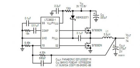
High Current Step-Down Controller Regulates to 0.6V
Published:2012/10/30 21:46:00 Author:muriel | Keyword: High Current , Step-Down Controller, Regulates , 0.6V
View full Circuit Diagram | Comments | Reading(834)
Dual Monolithic Buck Regulator
Published:2012/10/30 21:42:00 Author:muriel | Keyword: Dual Monolithic, Buck Regulator

View full Circuit Diagram | Comments | Reading(668)
Synchronous buck MOSFET loss calculations
Published:2012/10/30 21:28:00 Author:muriel | Keyword: Synchronous buck MOSFET

View full Circuit Diagram | Comments | Reading(696)
Typical Adaptive Gate drive
Published:2012/10/30 21:28:00 Author:muriel | Keyword: Typical Adaptive Gate drive

View full Circuit Diagram | Comments | Reading(598)
The LD7208 car turning alarm ASIC typical application circuit
Published:2012/10/30 21:15:00 Author:Ecco | Keyword: car turning alarm , ASIC, typical application

The main functions of the circuit: when operation is normal, the car light is intact, car light and bridge monitoring lamps flash at the same time, and the flashing frequency is 80 beats / min. Once the lights are damaged, the monitor lights flashing frequency will be doubled to show the alarm.
(View)
View full Circuit Diagram | Comments | Reading(993)
The basic application circuit of BA6104 5-bit LED level meter driver integrated circuit
Published:2012/10/30 21:21:00 Author:Ecco | Keyword: basic application , 5-bit, LED level meter, driver integrated circuit

BA6104's input stage uses PNP composite transistor base electrode input mode, so input impedance is very high. The output stage uses emitter follower form, adjusting the external resistor RL in figure can change the LED driving current. Pin 7 is connected to a resistor to change Vref, when pin 7 is open, reference voltage Vref is controlled by the internal IC, and its value is approximately 1V.
(View)
View full Circuit Diagram | Comments | Reading(1636)
DC motor reverse brake circuit
Published:2012/10/29 22:10:00 Author:Ecco | Keyword: DC motor l reverse brake

No matter in DC motor and AC motor system, due to the inertia of rotor and its transmission parts, the entire transmission system can completely stop over a period of time after rotating motor power is cut off. However, in the production process, it is required to stop motor in order to improve work efficiency, and even called for an immediate stop, so the effective braking measures must be taken to the motor.
(View)
View full Circuit Diagram | Comments | Reading(1409)
DC motor dynamic braking circuit
Published:2012/10/29 22:06:00 Author:Ecco | Keyword: DC motor l dynamic braking

When it is braking, pressing the stop button STP will make DC contactor KM be de-energized, the normally closed contact KM restores the closed state, so that the the voltage relay KV coil gets electric and moves, and its normally open contact KV is closed, then DC contactor KMB gets electric operation, the braking resistor R and armature M are connected in parallel. Excitation current direction has not changed, the torque generated by motor is the braking torque, so that the motor is rapidly stopped.
(View)
View full Circuit Diagram | Comments | Reading(1880)
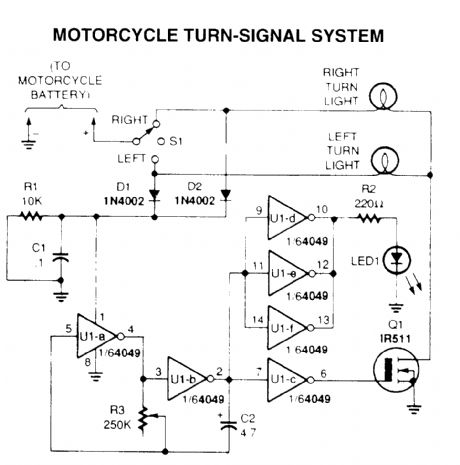
motorcycle turn-signal system
Published:2012/10/29 1:22:00 Author:muriel | Keyword: motorcycle turn-signal system
View full Circuit Diagram | Comments | Reading(2545)
The static driver interface circuit of SAA1064 serial I2C bus LED display driver integrated circuit
Published:2012/10/28 21:15:00 Author:Ecco | Keyword: static driver , interface , serial I2C bus , LED display , driver integrated circuit

Under static working mode, LED does not require to add an external driver, but it directly uses two 8-bit output port driver. Vcc and VEE ends are adding decoupling capacitors, the general value is 0.01μF.
(View)
View full Circuit Diagram | Comments | Reading(1455)
The basic application circuit of BL6124 5-bit LED level meter driver integrated circuit
Published:2012/10/28 22:12:00 Author:Ecco | Keyword: basic application , 5-bit , LED level meter , driver integrated circuit


LED current limiting circuit is used to limit LED current, the LED can be connected to a resistor in parallel or in series, and the circuit is shown in (a ) , ( b ). When working voltage is higher than 9V, the LED current terminal should be added a shunt resistor, the specific circuit with different Vcc values is shown in Figure.
(View)
View full Circuit Diagram | Comments | Reading(2327)
Low-pass filter (Integrator) circuit
Published:2012/10/26 21:03:00 Author:Ecco | Keyword: Low-pass filter, Integrator

The circuit is a simple low-pass filter, but also can be used as an integrator. When it is used as integrator, switch S1 is connected to input end, while the S2 is disconnected. R3 is connected when it is used as lower filter, amplification coefficient of the voltage VU=R3/R1. The internal resistor Ri of signal source is much less than R1, and R2 value should be equal to the equivalent value of R3 and R1 connected in parallel.
(View)
View full Circuit Diagram | Comments | Reading(958)
PC machine CPU overheating language telling circuit
Published:2012/10/26 21:53:00 Author:Ecco | Keyword: PC machine , CPU overheating, language telling

It consists of a temperature sensor, temperature control electronic switch and language telling circuit. In the summer season, central processing unit CPU on PC is often overheating, in the circuit, the tube core of VT1 is closed to radiator of CPU chip, once the CPU is overheating, the circuit will send out Please note the temperature to remind users to take cooling measures.
(View)
View full Circuit Diagram | Comments | Reading(1178)
High voltage DC switch circuit diagram
Published:2012/10/25 21:01:00 Author:Ecco | Keyword: High voltage , DC switch

The circuit uses optical-isolation optoelectronic thyristor rectifier as high voltage DC switch. When MCA2 photoelectric Darlene Dayton circuit's Q1 divides current of the load through gate, then the silicon controlled rectifier's gate gets bypass, silicon controlled rectifier is turned off. If the pulse signal is added to appropriate light emitting diode, the circuit operates, so that the thyristors are turned on or off.
(View)
View full Circuit Diagram | Comments | Reading(1433)
3-Way Linkwitz Riley Crossover
Published:2012/10/25 3:12:00 Author:muriel | Keyword: 3-Way , Linkwitz Riley Crossover

the way to connect a 3-Way crossover. This unit produces excellent results, with good phase coherency and a flat response across the entire frequency band.
I know the circuits look complicated, but each is basically repetition of a common circuit block - the filter section. Since the opamps are all used as unity gain buffers, the use of premium devices is not really essential, so the TL072 type would be quite serviceable in this role. Needless to say, if you want to use better devices (even discrete opamps) you can easily do so. Make sure that any device used is stable for unity gain - this is not always the case with some devices, especially when external compensation is used. In this case, use the manufacturer's recommended value of stability cap for unity gain operation. (View)
View full Circuit Diagram | Comments | Reading(8332)
2-Way Linkwitz Riley Crossover
Published:2012/10/25 3:12:00 Author:muriel | Keyword: 2-Way, Linkwitz Riley Crossover

the general concept for a full stereo version, with two identical filter sections (but without balanced inputs). With the component values shown, these have a crossover frequency of 310Hz (refer to the article on Bi-Amping to see the reason for my choice of frequency). This unit will provide a completely flat frequency response across the crossover frequency, with the signal from both filters remaining in phase at all times.
Note that the PCB version is almost identical, but offers the choice of a balanced or unbalanced input stage. It's not switchable, but the mode is selected before construction, and links or resistors are installed as needed.
(View)
View full Circuit Diagram | Comments | Reading(3378)
Output Buffers circuit
Published:2012/10/25 3:10:00 Author:muriel | Keyword: Output Buffers circuit

the output buffers (again, left channel only) connected in the manner I used for the prototype. The high pass section provides a gain of 6dB, and has a pot to adjust the level to allow for different loudspeaker sensitivities. The gain can be adjusted from +6dB to -8dB (approximately), which will be more than enough for any installation. The low pass buffer has a gain of -1, which is to say that gain is unity, but inverted. A phase switch can be incorporated as shown to allow for sub-woofer phase correction - this is not needed for a biamp setup. (View)
View full Circuit Diagram | Comments | Reading(653)
- 12dB / Octave Crossover Network
Published:2012/10/25 3:09:00 Author:muriel | Keyword: - 12dB , Octave, Crossover Network

The circuit diagram of the filter section is shown in Figure 1. It is a completely conventional filter, and the component designations are the same as for the 24dB unit described in Project 09. It is designed primarily for 2-way electronically crossed over systems, such as adding a subwoofer or biamping an existing loudspeaker system.
Figure 2 shows the output buffers - again using the same component designators, but with some changes. The low pass section is inverted, since 12dB crossovers always invert the phase of one signal. If desired, the high pass section may be inverted instead - see Figure 3 for the alternative version. (View)
View full Circuit Diagram | Comments | Reading(2216)
Expandable Graphic Equaliser
Published:2012/10/25 3:00:00 Author:muriel | Keyword: Expandable Graphic Equaliser

View full Circuit Diagram | Comments | Reading(596)
Crossover Networks
Published:2012/10/25 2:39:00 Author:muriel | Keyword: Crossover Networks

When combined, high pass and low pass filters are commonly used to create electronic crossover networks. There are many different ways to do this, but the most common is still the second order Butterworth filter. Although these are essentially at least as good as the passive speaker level counterpart (but not all that much better), the results are often vastly superior. The reasons for this are discussed at great length in my article Bi-Amplification - Not Quite Magic (but Close) and I shall not repeat them here.
In a nutshell, using an electronic crossover eliminates many of the problems that beset loudspeaker designers when they have to design and build the crossover network. The passive crossover is influenced by any aberration in the driver's impedance, especially at or near the crossover frequency. Since the electronic crossover supplies the signal to a separate amplifier for each frequency band, there is no interaction and each amp only needs to be concerned with a much smaller bandwidth.
All crossover networks are a combination of high pass and low pass filters, although this is not always achieved in the same way. Some crossovers use an opamp as a subtracting amplifier, so rather than using a separate filter, the bass (for example) is subtracted from the main signal to provide the midrange and high frequency. Alternatively, the mid+high output from the filter is subtracted from the main signal to separate the bass, and this configuration is shown below. These crossovers are phase coherent (both outputs are always in phase at any frequency), but are asymmetrical. A typical design is shown in Figure 19, and the response clearly shows that the high pass rolloff is 12dB/octave, but the low pass is only 6dB/octave. (View)
View full Circuit Diagram | Comments | Reading(1355)
| Pages:68/471 At 206162636465666768697071727374757677787980Under 20 |
Circuit Categories
power supply circuit
Amplifier Circuit
Basic Circuit
LED and Light Circuit
Sensor Circuit
Signal Processing
Electrical Equipment Circuit
Control Circuit
Remote Control Circuit
A/D-D/A Converter Circuit
Audio Circuit
Measuring and Test Circuit
Communication Circuit
Computer-Related Circuit
555 Circuit
Automotive Circuit
Repairing Circuit