
Basic Circuit
Index 66
Infra Red Extender Mark 5
Published:2012/11/21 1:55:00 Author:muriel | Keyword: Infra , Red , Extender
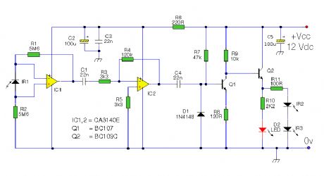
The latest addition to my collection of Infra Red (IR) Repeater circuits. The Mark 5 is a much improved version of the Mark 1 circuit and has increased range and sensitivity. It is also immune to the effects ofambient light, daylight and other forms of interference. In addition it works with IR modulation freuencies in the range 30 to 120kHz making the Mk5 circuit the best choice for compatibility with remote controls. (View)
View full Circuit Diagram | Comments | Reading(1036)
Infra Red Extender Mark 4
Published:2012/11/21 1:54:00 Author:muriel | Keyword: Infra, Red, Extender
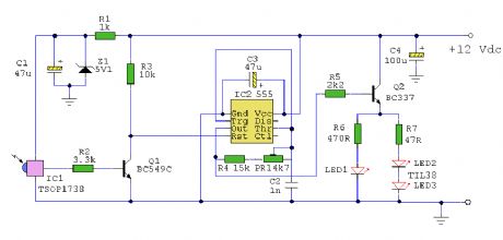
An Infra Red wired Repeater circuit to control appliances from a remote location. (View)
View full Circuit Diagram | Comments | Reading(733)
IR Remote Control Extender Mark 3
Published:2012/11/21 1:54:00 Author:muriel | Keyword: IR, Remote Control, Extender
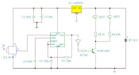
This Mark3 version of the Infra Red extender is a special version designed to control appliances that use high frequency modulated IR remote controls. (View)
View full Circuit Diagram | Comments | Reading(971)
IR Remote Control Extender Mark 2
Published:2012/11/21 1:53:00 Author:muriel | Keyword: IR , Remote Control, Extender
This is an improved IR remote control extender circuit. It has high noise immunity, is resistant to ambient and reflected light and has an increased range from remote control to the extender circuit of about 7 meters. It should work with any domestic apparatus that use 36-38kHz for the IR carrier frequency. Please note that this is NOT compatible with some satellite receivers that use 115KHz as a carrier frequency. (View)
View full Circuit Diagram | Comments | Reading(868)
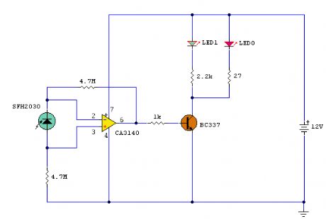
Infra Red Remote Control Extender
Published:2012/11/21 1:52:00 Author:muriel | Keyword: Infra , Red , Remote Control, Extender

This circuit is used to relay signals from an Infra Red remote control in one room to an IR controlled appliance in another room. (View)
View full Circuit Diagram | Comments | Reading(621)
Eight-way remote control transmitter CS901
Published:2012/11/20 21:07:00 Author:Ecco | Keyword: Eight-way , remote control, transmitter

The keys SA1 ~ SA8 and diodes VD1 ~ VD13 form Octal matrix input circuit for the eight encoded input circuit of remote control transmitter circuit. Because the SM5262's pin 7 to 13 are used for the address / data common terminals, if ther are used as the data input terminals, the circuit has a total of six data input terminals, when all of them are used for data input, they can form a total of 26 = 64, i.e. 64-channel remote control transmitter.
(View)
View full Circuit Diagram | Comments | Reading(908)
The Anti Shake circuit with NAND gate
Published:2012/11/20 21:04:00 Author:Ecco | Keyword: Anti Shake, NAND gate

Dither signal may occur in the conversion of digital electronic signal from chain mechanical switch, and it may cause misoperation, so the illustrated circuit may be used for this.
(View)
View full Circuit Diagram | Comments | Reading(679)
Automatically series reactance start three-phase motor circuit 2
Published:2012/11/20 0:39:00 Author:Ecco | Keyword: Automatically, series reactance, start, three-phase motor

As shown in figure, pressing the start button ST, then the KM1 coil will pull in, and the main contacts are connected to reactors group L, the motor M gets to the buck start state. At the same time, due to the closure of the the KM1 auxiliary contacts, time relay KT gets electric timing. When the delay time reaches KT's tuning time, KT contacts are closed, KM2 coil gets electric, the normally closed contact cuts KM1 coil loop, then the KT coils have also de-energized, KM2 normally open contact action to protect themselves.
(View)
View full Circuit Diagram | Comments | Reading(990)
Single phase shaded pole motor commutation circuit
Published:2012/11/20 2:17:00 Author:Ecco | Keyword: Single phase , shaded pole, motor commutation

Due to the stator structure and particularity of working principle, shaded pole motor can not use interchangeable winding terminals to change direction like the split-phase capacitor motor. The shaded pole motor's shaded pole split-phase effect can make the original magnetic field without rotating nature change into an approximation rotating magnetic field.
(View)
View full Circuit Diagram | Comments | Reading(1180)
The astable circuit
Published:2012/11/18 21:51:00 Author:Ecco | Keyword: Astable

When the left and right parts of circuit have the same capacitance and base resistance in the drawings, it outputs 50% duty cycle square wave signal.
(View)
View full Circuit Diagram | Comments | Reading(594)
Bistable circuit with multi- input side
Published:2012/11/18 21:43:00 Author:Ecco | Keyword: Bistable circuit , multi- input side

The circuit has two input terminals E10, E20, and two output terminals A1 , A2. When output terminal A1 is at the positive level, the circuit is in the 1 state and 0 state for 0 level. In addition, there are two additional dynamic inputs E1D, E2D, and corresponding preset input ends E1V, E2V. Only when the preset input terminal is 0 level, the pulse signals on input terminals E1D and E2D can make circuit flip to its positive level, then the input terminal is locked.
(View)
View full Circuit Diagram | Comments | Reading(822)
A window discriminator circuit with small hysteresis loop
Published:2012/11/18 21:29:00 Author:Ecco | Keyword: window discriminator , small hysteresis loop

Window Hysteresis Loop of the internal edge is hoped to be smaller in some applications, then the two circuits shown in figure can be used. The Figure a is only suitable for the occasions with TCA965 feet 9 voltage U9> 200mV. If it requires smaller U9 value, then the circuit shown in Figure b can be used.
(View)
View full Circuit Diagram | Comments | Reading(1252)
DC compound motor commutation circuit
Published:2012/11/16 2:29:00 Author:Ecco | Keyword: DC, compound motor , commutation

Excitation windings of such a motor is also formed by a parallel winding Ll and series winding, and it is shown in ( a ). In order to change the steering of the motor by changing excitation current, the direction of the current of L1 and L2 must be simultaneously changed, but such a change method is relatively trouble. The commonly used method is to change the direction of the armature winding current.
(View)
View full Circuit Diagram | Comments | Reading(966)
Line lamp transformer checking current transformer circuit
Published:2012/11/16 2:43:00 Author:Ecco | Keyword: Line lamp , transformer , checking , current transformer

10% error qualification of the current transformer has a direct impact on power system relay protection. If it is failed, it will cause current protection to refuse to move and the expansion of the accident, it must be calibrated periodically. The method to check current transformer by line lamp transformer is shown as the figure. Operation method: closing the knife-switch QS, slowly adjusting regulator TA will make line lamp transformer T's voltage gradually increase, then ammeter PA1 , PA2 reading will slowly increase.
(View)
View full Circuit Diagram | Comments | Reading(1032)
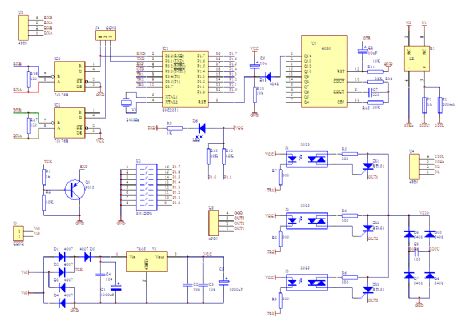
USB RDS Coder Board using ATmega32
Published:2012/11/15 20:59:00 Author:muriel | Keyword: USB , RDS, Coder Board , ATmega32


This board is a RDS coder using an ATMEL AVR ATmega32. This board can be controled by a RS232 link, USB interface or SPI. TA data is displayed wiyth a LED and can be controled by : - Hardware input - RS232 - USB - SPI (not yet implemented) (View)
View full Circuit Diagram | Comments | Reading(2956)
The speed control circuit without governor
Published:2012/11/13 20:34:00 Author:Ecco | Keyword: speed control , without governor
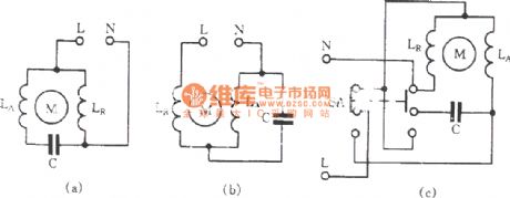
General capacitor start motor circuit is shown in (a), it uses capacitor phase shift to produce starting torque. If the motor winding connection is changed into series from parallel, as shown in Figure ( b ), at this time, the voltage of the main winding LR and the secondary winding LA is relatively lower than the parallel, it is equivalent of connecting a reactor in series in the circuit, then the motor speed natural declines.
(View)
View full Circuit Diagram | Comments | Reading(682)
JK1-125 auto buck starter circuit
Published:2012/11/12 19:43:00 Author:Ecco | Keyword: auto buck starter

In the figure, WJ is the energy saving and silent running device, you can use it to save energy and reduce noise.
(View)
View full Circuit Diagram | Comments | Reading(1149)
Capacitor start single-phase motor non- frequent commutation circuit
Published:2012/11/12 20:50:00 Author:Ecco | Keyword: Capacitor start, single-phase motor, non- frequent commutation
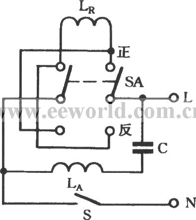
The resistance of motor's main winding LR and secondary winding LA is not equal, if it is measured with a multimeter, the winding without connecting to a capacitor C in series with smaller resistance is the main winding LR; the winding connected to capacitor C in series with larger resistance is the secondary winding LR. The working principle is shown in Fig. C is the secondary winding starting capacitor, it is typically 1μF, SA is a DPDT button switch KN3 -3 - 2 × 2.
(View)
View full Circuit Diagram | Comments | Reading(1055)
Network intelligent control Tap (data Tap )
Published:2012/11/11 21:52:00 Author:Ecco | Keyword: Network, intelligent control Tap, data Tap
Network intelligent control Tap is shown as the figure:
(View)
View full Circuit Diagram | Comments | Reading(637)
Typical Thermal Layout Considerations
Published:2012/11/9 0:13:00 Author:muriel | Keyword: Thermal Layout

View full Circuit Diagram | Comments | Reading(610)
| Pages:66/471 At 206162636465666768697071727374757677787980Under 20 |
Circuit Categories
power supply circuit
Amplifier Circuit
Basic Circuit
LED and Light Circuit
Sensor Circuit
Signal Processing
Electrical Equipment Circuit
Control Circuit
Remote Control Circuit
A/D-D/A Converter Circuit
Audio Circuit
Measuring and Test Circuit
Communication Circuit
Computer-Related Circuit
555 Circuit
Automotive Circuit
Repairing Circuit