Basic Circuit
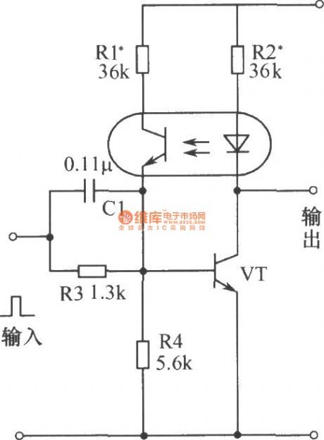
The bistable circuit with optocoupler and transistor
Published:2012/12/2 20:37:00 Author:Ecco | Keyword: bistable , optocoupler , transistor | From:SeekIC

In the initial state with the power turning on, the transistor VT is cutoff, the circuit outputs high potential. When the input terminal is coupled with a positive pulse, the collector current of VT increases, photocoupler light emitting diode emits light, and the collector-emitter resistance of phototransistor becomes smaller, then the base current of VT increases to form a positive feedback, so that VT quickly be saturated, and it changes to 0 from 1 . When it is input the negative pulse, the collector current of VT becomes small, thereby enabling light emitting diode darken, and VT's base current becomes small, causing the collector current of VT to be further reduced, the VT quickly become the OFF state, the light emitting diode does not emit light, the phototransistor is turned off, so that VT is stable in the off state, the state of flip-flop changes from 0 to l .
Reprinted Url Of This Article:
http://www.seekic.com/circuit_diagram/Basic_Circuit/The_bistable_circuit_with_optocoupler_and_transistor.html
Print this Page | Comments | Reading(3)

Article Categories
power supply circuit
Amplifier Circuit
Basic Circuit
LED and Light Circuit
Sensor Circuit
Signal Processing
Electrical Equipment Circuit
Control Circuit
Remote Control Circuit
A/D-D/A Converter Circuit
Audio Circuit
Measuring and Test Circuit
Communication Circuit
Computer-Related Circuit
555 Circuit
Automotive Circuit
Repairing Circuit
Code: