Basic Circuit
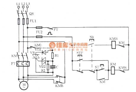
Bidirectional thyristor power consumption brake circuit
Published:2012/9/6 22:22:00 Author:Ecco | Keyword: Bidirectional thyristor , power consumption , brake | From:SeekIC

As shown in the figure, VS is the bidirectional thyristor, and its conduction angle determines the size of the braking energy; VD2 is the trigger tube, the 30V breakdown voltage enables VS reliable and stable trigger. VD1 is the rectifier diode, R2 is bleeder resistor to make the charge on the C be discharged at any time. R1, C form the phase shifting circuit to control the VS conduction angle, thereby providing an appropriate size of pulsating DC voltage for braking. C takes higher value, the braking time is longer; Conversely, the braking time is shorter. People can select appropriate capacitance of C to make brake average voltage be 85V, the brake current be 4.5 ~~ 5A, motor full load brake time be 4 to 5 seconds. KM is the main contact for the operation of the motor M, KMB is brake contactor of motor M.
Reprinted Url Of This Article:
http://www.seekic.com/circuit_diagram/Basic_Circuit/Bidirectional_thyristor_power_consumption_brake_circuit.html
Print this Page | Comments | Reading(3)

Article Categories
power supply circuit
Amplifier Circuit
Basic Circuit
LED and Light Circuit
Sensor Circuit
Signal Processing
Electrical Equipment Circuit
Control Circuit
Remote Control Circuit
A/D-D/A Converter Circuit
Audio Circuit
Measuring and Test Circuit
Communication Circuit
Computer-Related Circuit
555 Circuit
Automotive Circuit
Repairing Circuit
Code: