Basic Circuit
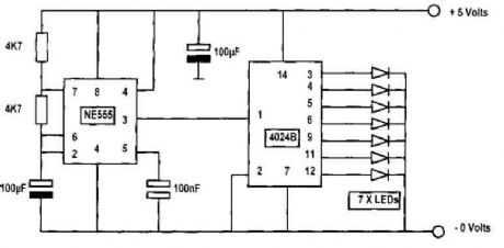
Binary Counter using 555 and 4042B
Published:2012/9/13 21:29:00 Author:Ecco | Keyword: Binary Counter | From:SeekIC

In this circuit diagram, an NE555 timer is used as a pulse generator producing pulses at about one-second duration. This is governed by the timing components connected to pins 2, 6, and 7. If the 100μF capacitor connected on pins 2 and 6 were reduced to 47μF, then the counting pulses will be about 1/2 second each. The output of the pulse generator at pin 3 is connected to pin 1 of the binary counter 4042B. The actual device is a 4042 but are usually advertised as CD4042BE, CD 4042BM, CD 4042BC and so on, but as far as we are concerned in this application they are all the same and will give the same results.....
Reprinted Url Of This Article:
http://www.seekic.com/circuit_diagram/Basic_Circuit/Binary_Counter_using_555_and_4042B.html
Print this Page | Comments | Reading(3)

Article Categories
power supply circuit
Amplifier Circuit
Basic Circuit
LED and Light Circuit
Sensor Circuit
Signal Processing
Electrical Equipment Circuit
Control Circuit
Remote Control Circuit
A/D-D/A Converter Circuit
Audio Circuit
Measuring and Test Circuit
Communication Circuit
Computer-Related Circuit
555 Circuit
Automotive Circuit
Repairing Circuit
Code: