
Amplifier Circuit
Index 102
UNIVERSAL_AUDIO_LINE_AMPLIFIER
Published:2009/7/9 3:17:00 Author:May
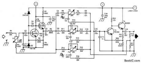
A line amplifier is always a useful unit to have around, whether it is for matching a line signal or raising its level somewhat. This might be needed during a recording session or with a public-address system. Furthermore, a line mixer can be constructed from a number of these amplifiers. The input of the amplifier is high-voltage proof. The output impedance is low.
The circuit is a conventional design: two dc-coupled stages of amplification are separated by a three-fold Baxandall tone control system. The volume control at the input is conspicuous by having its cold side connected, not to ground, but to the output of the first amplifier. Because the signal there is out of phase with the input signal, the amplifier obtains negative feedback via P1. The amplification is therefore inversely proportional to the magnitude of the input signal. Thus, it is possible for the amplifier to accept a wide range of input levels. It is quite possible to input a signal taken directly from the loudspeaker termi-nals of a power amplifier.
The supply voltage is 24 V. At that voltage, the amplifier draws a current of about 4 mA. If several amplifiers are used in conjunction (as, for instance, in a mixer panel), the various supplies (+ and ++ in the diagram) can be interlinked. Capacitors C17 and C18, and resistor R7 don't need to be duplicated in that case. (View)
View full Circuit Diagram | Comments | Reading(3608)
ELECTRIC_GUITAR_MATCHING_AMPLIFIER
Published:2009/7/9 3:13:00 Author:May
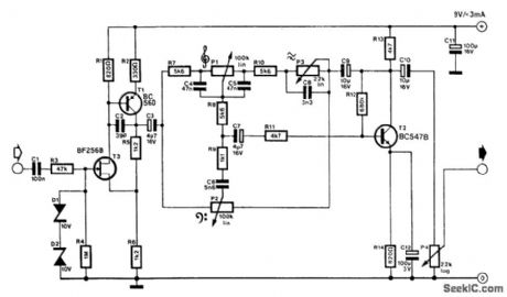
An electric guitar often has to be connected to a mixing panel, a tape deck or a potable studio. As far as cabling is concerned, that is no problem, but matching the high impedance of the guitar element to the low impedance of the line input of the mixing panel or tape deck is a problem. Even the so-called high impedance inputs of those units are not suitable for the guitar output. When the guitar is connected to such an input, hardly any signal is left for the panel or deck to process.
It would be possible to connect the guitar to the (high impedance) microphone input, but it is normally far too sensitive for that purpose; guitar clipping occurs all too readily.
The matching amplifier presented here solves those problems: it has a high-impedance (1 MΩ) input that can withstand voltages of over 200 V. The output impedance is reasonably low. Amplification is x 2 (6 dB). Dual tone control, presence control, and volume control are provided.
The circuit can handle input levels of up to 3 V. Above that level distortion increases, but that is, of course, a good thing with guitar music. Real clipping of the input signal does not occur until much higher levels than are obtainable from a guitar are applied. Power is supplied by a 9-V (PP3) battery from which the circuit draws a current that does not exceed 3 mA. (View)
View full Circuit Diagram | Comments | Reading(1226)
SIMPLE_MICROPHONE_PREAMP
Published:2009/7/9 3:09:00 Author:May
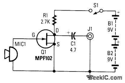
This preamp uses a small dynamic microphone coupled to the gate of Q1. R1 is a load resistor.Audio is taken out between the negative side of C1 and ground. Output will be between 10 and100 mVpp, depending on the microphone. (View)
View full Circuit Diagram | Comments | Reading(1075)
LOW_NOISE_1_000×PREAMP
Published:2009/7/9 3:08:00 Author:May
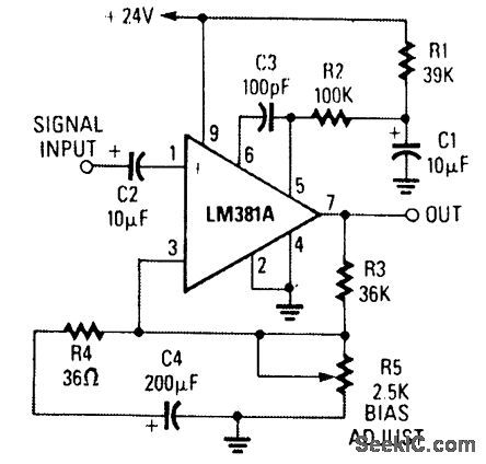
An LM381A is used here as a low-noise pre-amp with a gain of approximately 1 000 x. Adjust R5 for 12 V at pin 7, assuming a 24-V supply. (View)
View full Circuit Diagram | Comments | Reading(1361)
LOW_NOISE_AMPLIFIER
Published:2009/7/9 3:07:00 Author:May
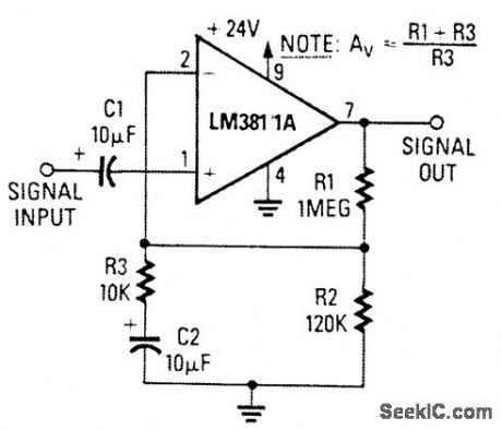
This low-noise LM381/1A noninverting ampli-fter has a gain of 100. (View)
View full Circuit Diagram | Comments | Reading(1841)
IMPEDANCE_MATCHING_PREAMP
Published:2009/7/9 3:06:00 Author:May
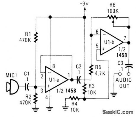
This circuit will match a crystal microphone to a device that requires a low-impedance dynamic microphone. (View)
View full Circuit Diagram | Comments | Reading(1414)
ULTRA_LOW_NOISE_MAGNETIC_PHONO_PREAMP
Published:2009/7/9 3:00:00 Author:May

This phono preamp uses an LM381/1Ain a cir-cuit that includes RIAA equalization. Adjust R7 fora voltage that is equal to half of the supply voltage(≈16.5 V). (View)
View full Circuit Diagram | Comments | Reading(1329)
SIMPLE_40_dB_GAIN_AMPLIFIER
Published:2009/7/9 2:58:00 Author:May
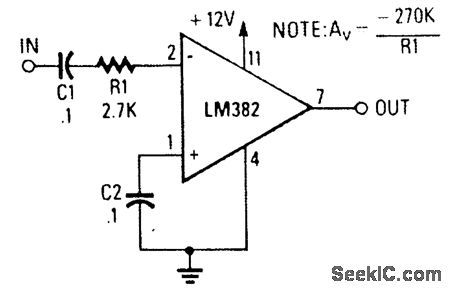
An LM382 low-noise preamp is used here to obtain a 40-dB gain amplifier, using only the IC and three peripheral components. (View)
View full Circuit Diagram | Comments | Reading(872)
LOW_NOISE_PHONO_PREAMP
Published:2009/7/9 2:57:00 Author:May

This circuit uses an LM381/1A as a low-noise phono preamp. The feedback network provides RIAA compensation. (View)
View full Circuit Diagram | Comments | Reading(2633)
SIMPLE_TAPE_PLAYBACT_AMPLIFIER
Published:2009/7/9 2:56:00 Author:May
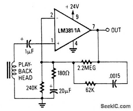
This circuit uses an LM381/1A as a tape pre-amp. The feedback network includes NAB Equali-zation. (View)
View full Circuit Diagram | Comments | Reading(947)
COLOR_VIDEO_AMPLIFIER
Published:2009/7/9 2:47:00 Author:May
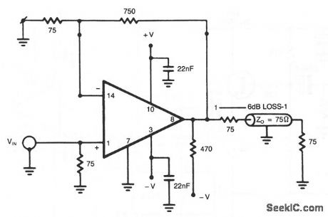
The NE5539 wideband op amp is easily adapted for use as a color video amplifier. The gain varies less than 0.5% from the bottom to the top of the stainase. The maximum differential phase is approximately + 0.1 °.The amplifier circuit was optimized for a 75-Ω input and output termination impedance for a gain of approximately 10 (20 dB). (View)
View full Circuit Diagram | Comments | Reading(0)
SIMPLE_OP_AMP_AUDIO_AMPLIFIER
Published:2009/7/9 2:43:00 Author:May

A CA3140 drives a complementary output stage Q1, Q2, and Q3. Output power depends on supply voltage and limits on dissipations of Q2 and Q3, but it can be 1 or 2 W with a higher impedance speaker and a 30-V supply. (View)
View full Circuit Diagram | Comments | Reading(889)
8_W_AUDIO_AMPLIFIER
Published:2009/7/9 2:41:00 Author:May
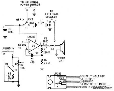
This audio power amp (built around an LM383 8-W, audio power amplifter) can be used to boost an audio signal to a sufficient level so that it can be heard in a high-noise environment. Note that LM383 should be heatsinked. (View)
View full Circuit Diagram | Comments | Reading(716)
LONG_NE_IR_DROP_VOLTAGE_RECOVERY
Published:2009/7/9 2:40:00 Author:May
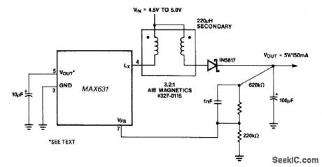
This circuit provides a unique solution to a common system-level power distribution problem: When the supply voltage to a remote board must traverse a long cable, the voltage at the end of the line some-times drops to unacceptable levels. This + 5-V/ + 5-V converter addresses this by taking the reduced volt-age at the end of the supply line and boosting it back to + 5 V. This can be especially useful in remote display devices, such as some point-of-sale (POS) terminals, where several meters of cable could separate the terminal from the readout. (View)
View full Circuit Diagram | Comments | Reading(510)
AUDIO_AMPLIFIER
Published:2009/7/9 2:40:00 Author:May
This amplifier will deliver around 20 W to an 8-Ω speaker. (View)
View full Circuit Diagram | Comments | Reading(0)
GENERAL_PURPOSE_5_W_AUDIO_AMPLIFIER_WITH_ac_POWER_SUPPLY
Published:2009/7/9 2:31:00 Author:May

This general-purpose low-power (5 W) audio amplifier is suitable for driving a speaker of approxi-mately 8 to 12 inches. A Sanyo LA4460 IC is used as the audio output IC. The circuit consists of a loud-ness control, driver amplifier Q1, and bass and treble controls of about ±10 dB boost/cut. It should be useful in a wide variety of situations. Either the ac supply shown can be used, or a 12 Vdc supply can be connected to points A&B (positive) and C (negative). Two of these circuits, using ganged potentiometers at R2, R7, and R11 can be used for stereo applications. T1 is a 12-V 1-amp plug-in transformer. Notice that IC1 must be heatsinked. Power output is about 5 W. A 4 x2 x0.050 aluminum heatsink should be adequate. (View)
View full Circuit Diagram | Comments | Reading(1406)
12_V_2O_W_STEREO_AMPLIFIER
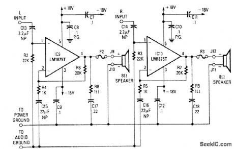
Published:2009/7/9 2:26:00 Author:May
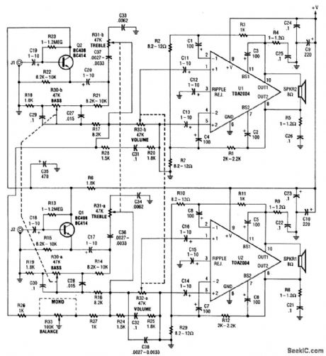
This amplirier 20W per channel. Input sensitivity is about 300mV into 47kΩ. Notice that a bridged output is used,so the speakers are operated with both wires above ground.A + 12-V supply is used. U1 and U2 must be heatsinked. (View)
View full Circuit Diagram | Comments | Reading(735)
WIRELESS_VIDEO_CAMERA_LINK
Published:2009/7/9 2:21:00 Author:May
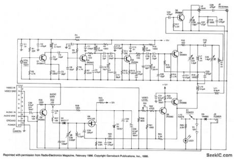
This high-performance video-camera link transmits signals from your video camera to your VCR, or from your VCR to TVs throughout your home. The first stage of the rf chain is a crystal-controlled oscillator, Q1, with a frequency of 60 to 65 MHz, which is one-eighth of the final output frequency. The oscillator produces a signal of about +6 dBm (4 mW) that drives three stages of frequency doublers. The combined action of those doublers multiplies the input frequency by eight for a final output frequency of (nominally) 500 MHz. Double-tuned circuits are used between each stage to help reduce spurious outputs that might cause unwanted interference. The video input signal from your VCR, video camera, etc. drives a video modulator, Q6 and Q7, that adds the video signal to the + 12 V line supplying power to the final doubler, Q4, and the output amplifier, Q5. That method of modulation is similar to the way a conventional AM-radio transmitter is modulated. The video modulator has a nominal bandwidth of five MHz. The audio input is applied to Q8, which operates as a VCO running at a nominal frequency of 4.5 MHz to produce the modulated sound carrier. For simplicity, Q8 is a free-running oscillator, since the ±25 kHz frequency deviation that is required would be very difficult to produce at that frequency with a crystal-controlled oscillator. Besides, most TV sound systems will accept a ± 10 kHz error in the sound-carrier frequency without producing undue distortion, and that greatly simplifies the circuitry required. The kit is available from North Country Radio, P.O. Box 53, Wykagyl Station, NY 10804. (View)
View full Circuit Diagram | Comments | Reading(862)
20_W_AUDIO_AMPLIFIER
Published:2009/7/9 2:20:00 Author:May
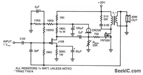
This amplifier delivers 20 W into an 8-Ω load using a single IRF520 driving a transformer coupled output stage.This circuit is similar to the audio output stage used in many inexpensive radios and phonographs.Distortion is less than 5% at 10 W,using very little feedback (3%),with the IRF520 biased at 3 A. (View)
View full Circuit Diagram | Comments | Reading(3261)
HYBRID_POWER_AMPLIFIER
Published:2009/7/9 2:16:00 Author:May
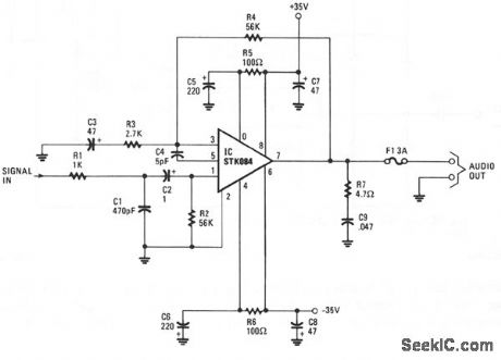
The input is ac coupled to the amplifier through C2, which blocks dc signals that might also be present at the input. The R1/C1 combination forms a low-pass filter, which eliminates unwanted high-frequency signals by bypassing them to ground when they appear at the circuit input, which has an impedance of about 52 Ω. The gain of the amplifier is set at about 26 dB by resistors R3 and R4. The R5/C5/C7 combination on the positive supply and its counterpart R6/C6/C8 on the negative supply provides power-supply decoupling. R7 and C9 together prevent oscillation at the output of the amplifier. From that point, the amplifier's output signal is direct coupled to the speaker through a 3-A fuse, F1. The dc output of the amplifier at pin 7 is 0 V, so no dc current flows through the speaker. Should there be a catastrophic failure of the output stage, fuse F1, which should be a fast-acting type, prevents dc from flowing through the speaker. (View)
View full Circuit Diagram | Comments | Reading(818)
| Pages:102/250 At 20101102103104105106107108109110111112113114115116117118119120Under 20 |
Circuit Categories
power supply circuit
Amplifier Circuit
Basic Circuit
LED and Light Circuit
Sensor Circuit
Signal Processing
Electrical Equipment Circuit
Control Circuit
Remote Control Circuit
A/D-D/A Converter Circuit
Audio Circuit
Measuring and Test Circuit
Communication Circuit
Computer-Related Circuit
555 Circuit
Automotive Circuit
Repairing Circuit