
Amplifier Circuit
Index 106
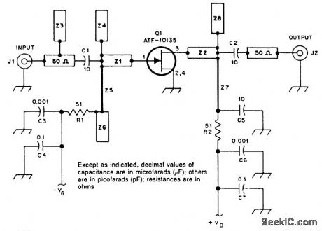
10_GHz_SINGLE_STAGE_PREAMP
Published:2009/7/8 22:45:00 Author:May

Using a single Avantek ATF 13135 GASFET, this preamplifier has 8-dB gain (typically)and1.7-dB nolse figure.The PC boardis 0.031'',doublesided,with E=2.2. (View)
View full Circuit Diagram | Comments | Reading(738)
57_GHz_MICROWAVE_AMPLIFIER
Published:2009/7/8 22:41:00 Author:May
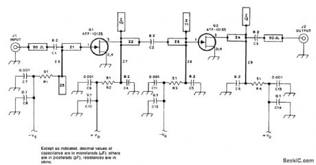
This preamplifier has a typical gain of 17 dB and NF=1.2 dB or better. If a 0.031 PC board (with a dielectric constant of 2.2) is used, the reverse side is unetched. (View)
View full Circuit Diagram | Comments | Reading(892)
23_GHz_MICROWAVE_PREAMP
Published:2009/7/8 22:32:00 Author:May
This low-noise amplifier requires no tuning, has a gain of 13 dB, and a typical NF of 0.6 dB at 2.3 GHz. (View)
View full Circuit Diagram | Comments | Reading(510)
OPERATIONAL_AMPLIFIERS
Published:2009/7/8 22:12:00 Author:May
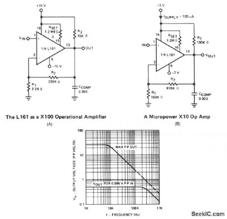
This is a single gain-of-100 amplifier with a gain-bandwidth product of 20 MHz! The primary limitation in the performance is the low slew rate (0.3 V/μs) imposed by IOH charging CCOMP. The effects of slew rate and compensation are shown. A lower gain amplifier requires a larger CCOMP, which in turn further reduces slew rate. For this reason, it might actually be advantageous in certain areas to lower the gain by placing a resistive divider at the input rather than raising RI. Figure 66-1B shows a 700-μW, X10 op amp whose slew rate is 0.02 V/μs and is 3 dB down at 100 kHz. (View)
View full Circuit Diagram | Comments | Reading(719)
AM_detector_AGC_amplifier_and_SSB_demodulator
Published:2009/7/23 21:39:00 Author:Jessie

The SL623 shown provides all three functions on a single chip, and is designed specifically for used in SSB/AM receivers (in conjunction with SL610/SL611/SL612 RF and IF amplifiers). With the values shown, typical characteristics are: SSB audio output 30 mV (rms), AM audio output 55 mV (rms), AGC range 6 dB (change in input level to increase AGC output voltage from 2.0 to 4.6 V), with an input impedance of 800Ω at pins 6/9, maximum frequency 30 MHz, and an AM carrier level down to 100 mV. (View)
View full Circuit Diagram | Comments | Reading(1624)
ADJUSTABLE_GAIN_WIDEBAND_AMPLIFIER
Published:2009/7/8 21:58:00 Author:May
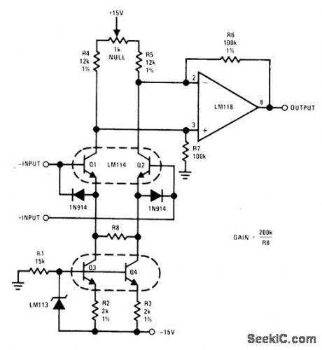
Single resistor R8 adjusts gain from less than1 to over 1000, with gain value equal to 200,000 divided by value in ohms used for R8 Commonmode rejection ratio is about 100 dB, independent of gain. Q1-Q2 are operated open-loop as floating differential input stage. Current sources Q3 and Q4 set operating current of input transistors.- Linear Applications, Vol.2, National Semiconductor, Santa Clara, CA, 1976, LB-21. (View)
View full Circuit Diagram | Comments | Reading(636)
DIFFERENTIAL_INPUT_AMPLIFIER
Published:2009/7/8 21:44:00 Author:May
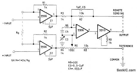
Provides gain up to 1000, depending on value of Rg, for video signals in radar, medical ultrasound,laser communication, and laser rangefinder applications. Uses three Optical Electronics 9906 wideband opamps and 9910 current booster for cable ddve. Bandwidth is above 10 MHz for gains of 0.1 to 100, decreasing to 5 MHz at gain of 1000. Miller compensation of input amplifiers minimizes noise level and gives input impedance of 5 megohms and 5 pF.- Wide Band Instrumentation Amplifier, Optical Electronics, Tucson, AZ, Application Tip 10276. (View)
View full Circuit Diagram | Comments | Reading(1661)
STRAIN_GAGE_AMPLIFIER
Published:2009/7/8 21:33:00 Author:May
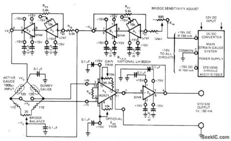
Optimum performance is achieved in fully portable system by utilizing combination of 747 opamps for A1 and A2 with National LH002CH opamp for B1-B3 and special AD521K instrumentation amplifier for output stage. Bypass capacitors suppress undesirable high-frequency signals. Stevens-Arnold DC/DC converter operating from 12-V storage battery provides required regulated ±15 VDC for system while giving excellent power isolation.-D. Sheehan, Strain-Gauge Transducer System Uses Off-the-Shelf Components, EDN Magazine, Nov. 5, 1977, p 79-81.
(View)
View full Circuit Diagram | Comments | Reading(2462)
METER_AMPLIFIER
Published:2009/7/8 21:28:00 Author:May

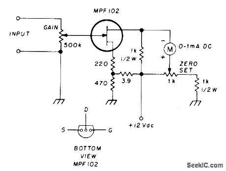
Junction FET in simple DC amplifier circuit converts 0-1 mA DC milliammeter to 0-100μADC microammeter. Adjust zero-set control for zero meter current with no input, then apply input signal and adjust gain to desired value.-N. J. Foot, Electronic Meter Amplifier, Ham Radio, Dec. 1976, p 38-39. (View)
View full Circuit Diagram | Comments | Reading(2760)
MOSFET_DIFFERENTIAL_AMPLIFIER
Published:2009/7/8 20:43:00 Author:May
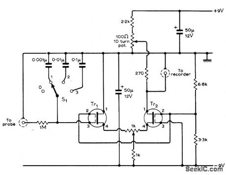
Developed to monhor chemical process of titration, by recording probe output voltages between 100 and 400 mV when intemal impedance of probe is in gigohm range. Either40673 or3N187 dualgate MOSFETs connected as differential arnpliiier are suitable for meeting high input re sistance requirement. Transistor level drifts because of temperature are in opposition and tend to cancel each other. Overall power gain of amplifier is about 70 dB. Circuit is suitable for other electrometer applications as well.-D. R. Bowman, Automatic Titration Potentiometer, Wireless World, Aug. 1971, p 400-401. (View)
View full Circuit Diagram | Comments | Reading(1082)
THERMOCOUPLE_AMPLIFIER
Published:2009/7/8 5:28:00 Author:May
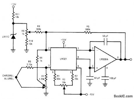
Combination of LM321 preamp and LM30SA opamp forms precision low-drift amplifier that includes compen-sat;on for ambient temperature variations.LM113 zener provides temperature-stable reference for offsetting output to read thermocouple temperature directly in degrees C. R4, R6, and R7 should be wirewound.-R. C. Dobkin, Versatile IC Preamp Makes Thermocouple Am-plifier with Cold Junction Compensation, Na-tional Semiconductor, Santa Clara, CA, 1973, LB-24. (View)
View full Circuit Diagram | Comments | Reading(0)
107_MHz_LIMITING_AMPLIFIER
Published:2009/7/8 5:12:00 Author:May
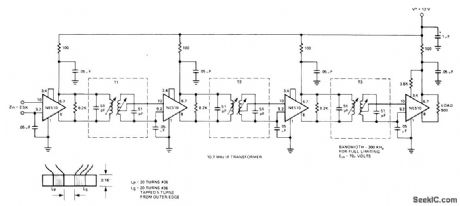
Uses SignetIcs NE510 transistor arrays in common-collector common-base configuration as IF strip for commercial FM broadcast receivel, Bandwidth is 300 kHz, achieved by ad justing transformers for 600-kHz bandwidth and using dual cup-core transformers originally designed for tubes.Windings were changed to give critical coupling Full limitingis provided by circuit with input voltage of 70 μVRMS.-''Signetics Analog Data Manual,″ Signetics Sunnyvale,CA,1977,p 747-748. (View)
View full Circuit Diagram | Comments | Reading(623)
BRIDGE_TYPE_AC_SERVO_AMPLIFIER
Published:2009/7/8 5:08:00 Author:May
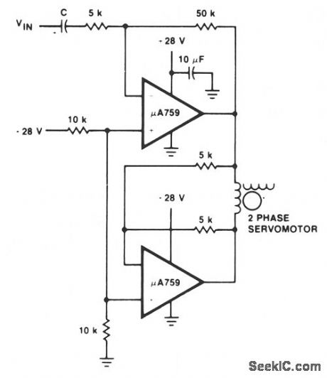
This motor driver circuit uses a μA759 power amplifter to drive a two-phase servomotor. (View)
View full Circuit Diagram | Comments | Reading(597)
LOW_DRIFT_SAMPLE_AND_HOLD
Published:2009/7/20 21:41:00 Author:Jessie
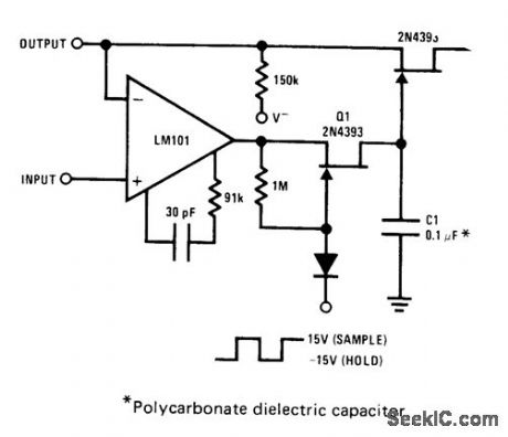
JFETs provide complete buffering to sample-and-hold capacitor C1. During sample, al is turned on to provide charging path. During hold, Q1 and Q2 are turned off so discharge paths through transistors for C1 are each less than 100 pA.Q2 also serves as buffer for opamp so feedback and out-put current are supplied only from opamp source.- FET Databook, National Semiconductor, Santa Clara, CA, 1977, p 6-26-6-36. (View)
View full Circuit Diagram | Comments | Reading(0)
7__10__15__20__25__35_watt_AF_power_amplifier_with_NPN_driver
Published:2009/7/20 21:26:00 Author:Jessie
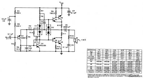
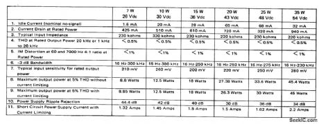
7-/10-/15-/20-/25-/35-watt AF power amplifier with NPN driver (courtesy Motorola Semiconductor Products Inc.). (View)
View full Circuit Diagram | Comments | Reading(1217)
DUAL_OPAMP_PREAMP
Published:2009/7/20 22:38:00 Author:Jessie
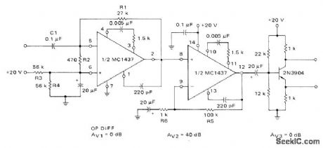
First section of Motorola MC1437 dual opamp is connected as operational differentiator driving direct-coupled noninverting opamp. Single-ended output is converted to push-pull by following phase-split-ting amplifier for driving power amplifier of 115-V 60-Hz servomotor.-A. Pshaenich, Servo Motor Drive Amplifiers, Motorola, Phoenix, AZ, 1972, AN-590. (View)
View full Circuit Diagram | Comments | Reading(1098)
PARALLEL_OPAMP_PREAMP
Published:2009/7/20 22:58:00 Author:Jessie

Provides differential output required for driving power amplifier of 115-V 60-Hz servomotor. One opamp section is connected inverting and the other noninverting to give required complementary outputs, Voltage gain is 40 dB, operating from single 20-V zener-regulated supply. High DC feedback gives excellent DC stability. Band-width is about 6 kHz. Input is driven by 90° phase shifter.-A. Pshaenich, Servo Motor Drive Amplifiers, Motorola, Phoenix, AZ, 1972, AN-590. (View)
View full Circuit Diagram | Comments | Reading(865)
28_V_PUSH_PULL_POWER_AMPLIFIER
Published:2009/7/20 22:57:00 Author:Jessie
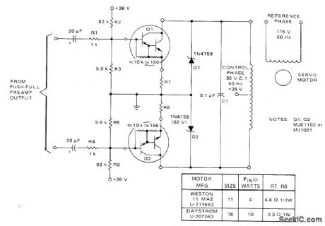
Power Darlingtons are used in common-emitter con-figuration to give high current gain for driving control phase of 60-Hz servo while providing high input impedance for preamp. No trans-formers are required. Darlingtons require heatsinks. Suitable for driving size 11 servo at 4 W and size 18 at 10 W if emitter resistors R7 and R8 are changed as in table.-A. Pshaenich, Servo Motor Drive Amplifiers, Motorola, Phoenix, AZ, 1972, AN-590. (View)
View full Circuit Diagram | Comments | Reading(653)
45_MHz_58_MHz_RF_amplifier
Published:2009/7/20 23:23:00 Author:Jessie
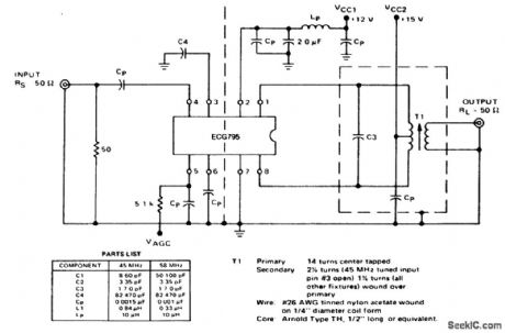
45 MHz/58 MHz RF amplifier. See listing for component values (courtesy GTE Sylvania Incorporated). (View)
View full Circuit Diagram | Comments | Reading(551)
ELECTRONICALLY_CONTROLLED_BANDWIDTH_
Published:2009/7/21 6:23:00 Author:Jessie
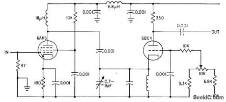
For search radar, potentiometer adjusts bias on 6BC4 tube of 30-Mc i-f preamp to vary bandwidth over range of 200 kc to 15 Mc.-Variable Bandwidth Preamplifier Electronically Varied Between 15 Mc and 200 Kc, Electronics, 35:2, p 102. (View)
View full Circuit Diagram | Comments | Reading(897)
| Pages:106/250 At 20101102103104105106107108109110111112113114115116117118119120Under 20 |
Circuit Categories
power supply circuit
Amplifier Circuit
Basic Circuit
LED and Light Circuit
Sensor Circuit
Signal Processing
Electrical Equipment Circuit
Control Circuit
Remote Control Circuit
A/D-D/A Converter Circuit
Audio Circuit
Measuring and Test Circuit
Communication Circuit
Computer-Related Circuit
555 Circuit
Automotive Circuit
Repairing Circuit