
Amplifier Circuit
Index 105
3_watt_differential_output_power_amplifier_using_two_MC1554s
Published:2009/7/21 2:17:00 Author:Jessie

3-watt differential output power amplifier using two MCl554s (courtesy Motorola Semiconductor Products Inc.). (View)
View full Circuit Diagram | Comments | Reading(615)
HARTLEY_VFO_WITH_BUFFER_AMPLIFIER
Published:2009/7/21 2:18:00 Author:Jessie

The figure shows a Hartley oscillator with buffer amplifier. This circuit can be tuned via C1, or if C1 is removed and the varactor network is connected to point A, a tuning voltage can be used instead. For best stability, L1 can be replaced with an air-core unit. Frequency range is 2 to 5 MHz, but the circuit can operate 1 to 10 MHz with suitable values of L1, C2, C3, C4, and C5. (View)
View full Circuit Diagram | Comments | Reading(1449)
Summing_scaling_amplifier_using_an_MC1552G
Published:2009/7/21 2:19:00 Author:Jessie
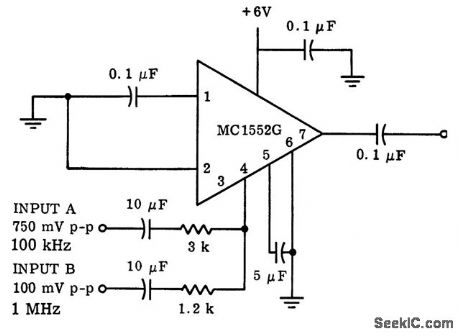
Summing/scaling amplifier using an MC1552G. Scaling considerations are accomplished by adjustment of the input resistors (courtesy Motorola Semiconductor Products Inc.). (View)
View full Circuit Diagram | Comments | Reading(568)
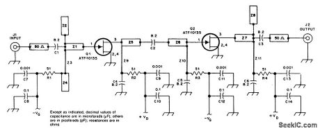
10_GHz_2_STAGE_PREAMP
Published:2009/7/8 23:11:00 Author:May
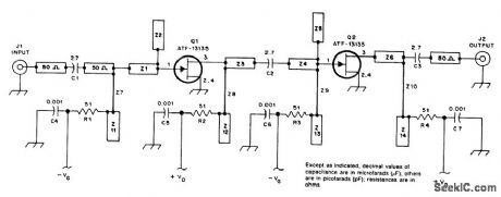
This preamp uses two ATF 13135 stages for typically 17-dB gain and less than 2 dB NF. (View)
View full Circuit Diagram | Comments | Reading(576)
True_PMS_circuit_using_one_AD531_multiplier_divider_and_two_AD741_op_amps
Published:2009/7/21 2:49:00 Author:Jessie

True PMS circuit using one AD531 multiplier/divider and two AD741 op amps. The AD531 is combined with a simple filter to obtain the true PMS value of an AC input signal. By scaling VOUT=10 volts DC for a ±10-volt DC input this circuit can give direct RMS readings for 100 hertz to 100 kilohertz sine waves from 0.2 volt to 7.0 volts peak (courtesy Analog Devices, Inc.). (View)
View full Circuit Diagram | Comments | Reading(801)
Precision_AGC_circuit_using_an_AD531_multiptter_divider_and_an_AD741_op_amp
Published:2009/7/21 2:52:00 Author:Jessie
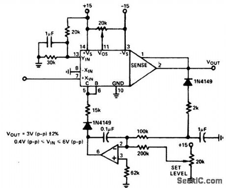
Precision AGC circuit using an AD531 multiptter/divider and an AD741 op amp. The circuit works by rectifying a signal and comparing it with thevoltage at the set level pot. The comparator output is then applied as a control signal to the AD531. The circuit can regulate VOUT to 3 volts peak to peak for inputs from 0.4 volt peak to peak to 6.0 volts peak to peak from 30 hertz to 400 kilohertz (courtesy Analog Devices, Inc.). (View)
View full Circuit Diagram | Comments | Reading(1181)
1_watt_inverting_power_amplifier_using_an_MC1554
Published:2009/7/21 2:53:00 Author:Jessie
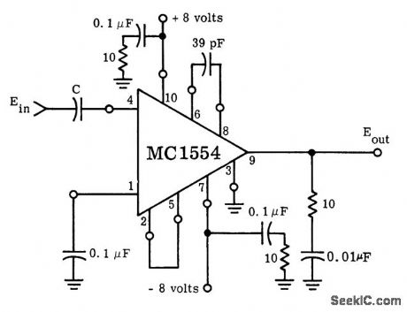
1-watt inverting power amplifier using an MC1554. As shown the voltage gain is 35. An external heat sink is required for dissipation greater than 350 mW (courtesy Motorola Semiconductor Products Inc.). (View)
View full Circuit Diagram | Comments | Reading(661)
Pulse_power_amplifier_using_an_MC1554
Published:2009/7/21 2:54:00 Author:Jessie

Pulse power amplifier using an MC1554. As shown voltage gain is 18. Peak power of 3 watts is possible (courtesy Motorola Semiconductor Products Inc.). (View)
View full Circuit Diagram | Comments | Reading(587)
BIAS_SUPPLY_FOR_MICROWAVE_PREAMPS
Published:2009/7/8 23:07:00 Author:May


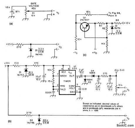


These two circuits provide bias for the microwave preamps shown in this text. The circuit in Fig.51-5(a) is a simple passive supply. Figures 51-5(b) and 51-5(c) are active supplies, with U1 generating a negative supply and Q1 setting the drain voltage and current, independent of GASFET haracteristics.
(View)
View full Circuit Diagram | Comments | Reading(593)
Stable_instrument_amplifier_for_lab_equipment_and_panel_meters
Published:2009/7/21 2:59:00 Author:Jessie

Stable instrument amplifier for lab equipment and panel meters. The amplifier is noninverting and offers selectable gains from 1 to 1000 in decade steps. Input impedance is 10M (courtesy Analog Devices, Inc.). (View)
View full Circuit Diagram | Comments | Reading(610)
400_Hz_AMPLIFIER
Published:2009/7/21 1:32:00 Author:Jessie
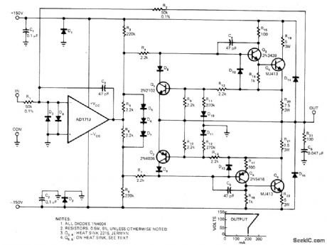
Developed to increase output power of digital-to-synchro converter systems while providing stable and accurate output and overall gain even with reactive loads, at Includes overload protection. Delivers 95 VRMS 400 Hz continuously into 500-ohm load. Power bandwidth is about 20 kHz. Foldback current limiting drops short-circuit current to 200mA when load exceeds 300 mA.-F. H. Catter-molen and J. A. Pieterse, Digital/Synchro Amplifier Features Overload Protection, EDN Magazine, Nov. 5, 1977, p 107-108. (View)
View full Circuit Diagram | Comments | Reading(2718)
Analog_multiplier_using_an_ECG947_dual_operational_amplifier
Published:2009/7/21 2:03:00 Author:Jessie

Analog multiplier using an ECG947 dual operational amplifier. The ECG947 is short-circuit protected and requires no external components for frequency compensation (courtesy GTE Sylvania Incorporated). (View)
View full Circuit Diagram | Comments | Reading(713)
PHOTODIODE_SOURCE_FOLLOWER
Published:2009/7/8 22:58:00 Author:May
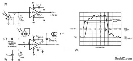
A common method of transforming the output current of a photodiode into a voltage signal, paralleling the photodiode with a high-value load resistor, produces a nonlinear response. Also the combination of the load's transresistance, RT, and the photodiode's junction capacitance, CJ, slows the circuit's response time. Figure 67-11B shows virtually the same components as Fig. 67-11A rearranged to maximize the inherent speed and linearity of the photodiode. The SP4010 (available from Hybrid Systems, Billerica, MA) is a unity voltage-gain buffer with a JFET input, 60-MHz 3-dB bandwidth, and 18-bit, 0.0004%, line-arity over a ± 10 V input range.
In the circuit of Fig. 67-11B, the photodiode sees a constant voltage across its terminals, which is essential for linear photodiode outputs. The optional zener diode, DZ, sets a reverse bias at the photo-diode for lower junction capacitance and higher speed. If y
ou don't use DZ, be sure to connect the feed-back loop. An optional diode, DCLAMP, limits the output in case of unexpected light bursts, but results in increased dark-current leakage and lower speed. The buffered output of the circuit equals the photodiode current times the transresistance, RT. Figure 67-11C shows the circuit's response to a fast light pulse.
(View)
View full Circuit Diagram | Comments | Reading(1101)
KA2182/KA2183 (TV) infrared remote control receiving preamplifier circuit
Published:2011/7/27 19:20:00 Author:TaoXi | Keyword: TV, infrared, remote control, receiving, preamplifier circuit
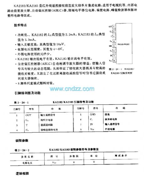
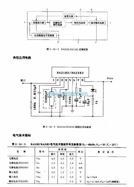
The KA2182/KA2183 is designed as the infrared remote control receiving preamplifier silicon single chip circuit that can be used in the TV application. The internal circuit is composed of the preamplifier, the Automatic bias controller (ABLC), amplitude limiting level shift circuit,biasing circuit, peak value detector and the pulse plastic circuit.
Features
Low power consumption. The Icc typical value of the KA2182 is 2.2mA, the Icc typical value of the KA2183 is 2.3mA.High input sensitivity, the typical value is 50uV.Wide input voltage range, the value is 4-8V.Little external components.The output low level of the KA2182 is effective, The output high level of the KA2183 is effective.
(View)
View full Circuit Diagram | Comments | Reading(593)
KA2184 (TV and video recoder) remote control receiving preamplifier circuit
Published:2011/7/27 20:21:00 Author:TaoXi | Keyword: TV, video recoder, remote control, receiving, preamplifier circuit
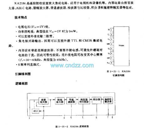
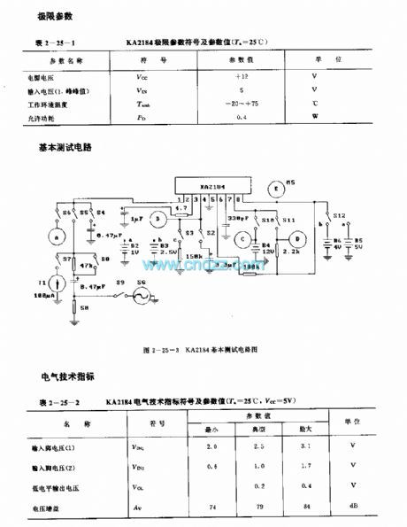
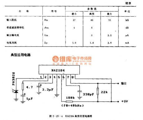
The KA2184 is designed as one kind of remote control receiving preamplifier circuit that can be used in the TV and video recoder applications. The internal circuit is composed of the preamplifier, the ABLC circuit, the amplitude limiting circuit, the bandpass filter, the wave detector, the comparator, the integrator, the Schmitt trigger.
Features
The power voltage is low (Vcc=5V).The power consumption is low, the typical value is 9mW when the typical value is 5V.It can be connected with the photosensitive diode directly.The collector is in the open-circuit output state, so you can connected it with the TTL and CMOS directly.It has the bandpass filter frequency selection filter.
(View)
View full Circuit Diagram | Comments | Reading(830)
LA7224 (TV and video recorder) infrared remote control receiving preamplifier circuit
Published:2011/7/27 20:35:00 Author:TaoXi | Keyword: TV, video recorder, infrared, remote control, receiving, preamplifier circuit
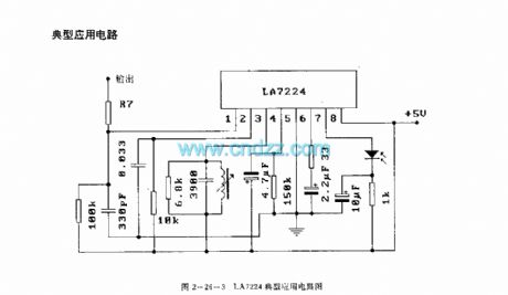
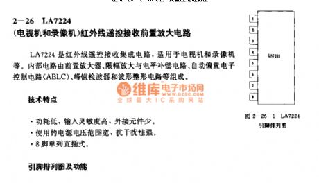
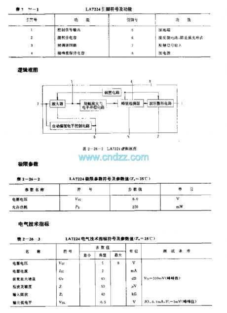
The LA7224 is designed as the infrared remote control receiving preamplifier circuit that can be used in the TV and video recorder applications. The internal circuit is composed of the preamplifier circuit, the amplitude limiting amplifier and level compensation circuit, the automatic bias level control circuit (ABLC), the peak value wave detector and the waveform plastic circuit.
Features
Low power consumption, high input sensitivity, little external components.The power voltage range is wide, the anti-interference performance is good.8-pin single DIP package.
(View)
View full Circuit Diagram | Comments | Reading(1333)
KA2181 (TV and video recoder) infrared remote control receiving preamplifier circuit
Published:2011/7/27 21:02:00 Author:TaoXi | Keyword: TV, video recoder, infrared, remote control, receiving, preamplifier circuit
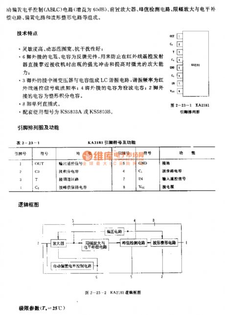
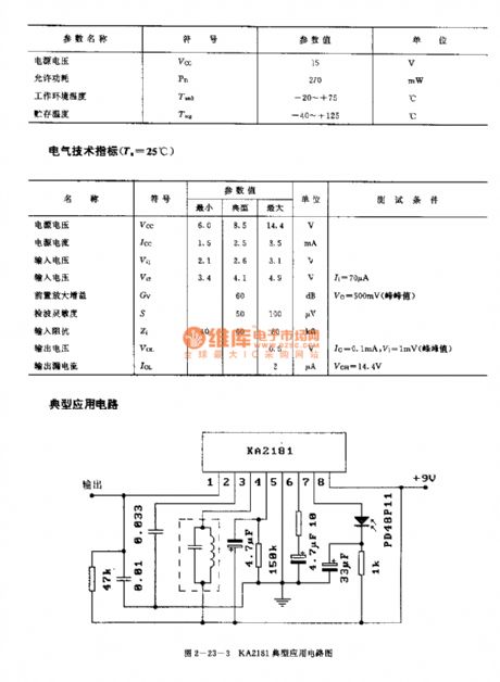
The KA2181 is designed as the infrared remote control receiving preamplifier circuit that can be used in the TV and video recoder applications. The internal circuit is composed of the automatic bias level control circuit (ABLC), the preamplifier circuit, the peak value detector, the amplitude limiting amplifier and level compensation circuit, the biasing circuit and the waveform plastic circuit.
Features
High sensitivity, wide dynamic range, good anti-interference performance.The external resistances and capacitances of pin-6 are the feedback components.The LC resonant circuit is composed of the medium frequency transformer and the capacitance.The 8-pin single row DIP package.The matching models are KS5803A or the KS5803B.
(View)
View full Circuit Diagram | Comments | Reading(681)
LJA7225 (Video recorder and TV set) infrared remote control receiving preamplifier circuit
Published:2011/7/27 21:46:00 Author:TaoXi | Keyword: Video recorder, TV set, infrared, remote control, receiving, preamplifier circuit
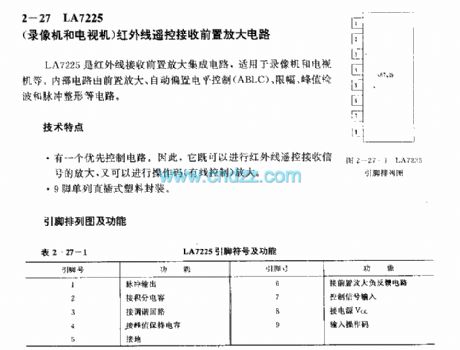
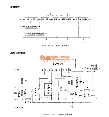
The LJA7225 is designed as the infrared remote control receiving preamplifier circuit that can be used in the video recorder and TV set applications. The internal circuit is composed of the preamplifier circuit, the automatic bias level control circuit (ABLC), the amplitude limiting circuit, the peak value wave detection circuit, the waveform plastic circuit.
Features
It has the priority control circuit, so it can amplify the infrared remote control receiving signal and the operation code.It is in the 9-pin single row DIP plastic package.
(View)
View full Circuit Diagram | Comments | Reading(621)
34_GHz_MICROWAVE_PREAMP
Published:2009/7/8 22:48:00 Author:May
At 3.45 GHz, this 2-stage preamp has a gain of 23 dB (typical) and less than 1dB NF. (View)
View full Circuit Diagram | Comments | Reading(476)
Precision_amolifier_with_closed_loop_voltage_gain_of_1000_using_an_ECG925
Published:2009/7/21 3:03:00 Author:Jessie
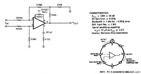
Precision amolifier with closed loop voltage gain of 1000 using an ECG925. Typical supplyvoltage is ±15 volts, but it can be powered with 6 supplies from ±3 volts to ±22 volts (courtesy GTE Sylvanta Incorporated). (View)
View full Circuit Diagram | Comments | Reading(683)
| Pages:105/250 At 20101102103104105106107108109110111112113114115116117118119120Under 20 |
Circuit Categories
power supply circuit
Amplifier Circuit
Basic Circuit
LED and Light Circuit
Sensor Circuit
Signal Processing
Electrical Equipment Circuit
Control Circuit
Remote Control Circuit
A/D-D/A Converter Circuit
Audio Circuit
Measuring and Test Circuit
Communication Circuit
Computer-Related Circuit
555 Circuit
Automotive Circuit
Repairing Circuit