
Amplifier Circuit
Index 119
+15_V_WITH_DIFFERENTIAL_AMPLIFIER
Published:2009/7/6 2:07:00 Author:May

Series regulator uses differential amplifiel as controlcircuit in which one side is referenced to zener and other to fraction of output voltage Second zener provides coarse regulated voltage to differential pair.-H.Olson、Power-Supply Servicing Ham Radio,Nov.1976、p44-50 (View)
View full Circuit Diagram | Comments | Reading(1764)
IMPROVED_PREAMP
Published:2009/7/6 2:04:00 Author:May

Replaces inefficient input circuit of inexpensive frequency counter, to ensure accurate counting from DC to over 60 MHz Circuit brings input signal waveform to TEL level of 3.5 V P-P while providing required perfect square waves down to lowest-frequency input signal. Input circuit is balanced FET source-follower having extremely high input impedance. Back-to-back diodes provide overload protection. Input stage drives 733 differential video amplifier having 100-MHz band-width and gain of 400. 2N709 switching transistor squares preamp signal for TTL translator using two sections of 74H00 high-speed quad NAND gate. Circuit requires dualpolarity sup ply delivering at least 63 mA; regulation is optionaL-G. Beltrami, High-Impedance Preamp and Pulse Shaper for Frequency Counters, Ham Radio, Feb. 1978, p 47-49.
(View)
View full Circuit Diagram | Comments | Reading(4942)
200_MHz_BUFFER
Published:2009/7/6 2:01:00 Author:May
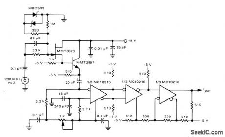
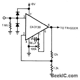
Developed for use ahead of prescaler in 200-MHz auto ranging frequency counter. Provides high input impedance to count-sensing device. Circuit includes Schmitt trigger action. Sensitivity is about 50 mV P-P.-T. Balph, A 200 MHz Autoranging MECL-McMOS Frequency Counter, Motorola, Phoenix, AZ, 1975, AN-742,p 10. (View)
View full Circuit Diagram | Comments | Reading(3133)
REMOTE_CONTROL_OF_AMPLIFIER_GAIN
Published:2009/7/23 21:40:00 Author:Jessie

Permits control of gain of small signal amplifier by means of d-c voltage. Adjustment potentiometer does not carry signal cur rent. D-c control voltage acts on 6-v zener diode which in turn controls amplifier gain. Control voltage is limited to -4 v, which makes gain adjustable between 0.04 and 0.7 for range of 1 to 18. Input signal is 1 V pp sine wave.-T. Molligna, Amplifier with DC Controlled Gain, EEE, 11:5, p 94-96. (View)
View full Circuit Diagram | Comments | Reading(994)
Simple_voltage_reference
Published:2009/7/23 21:40:00 Author:Jessie
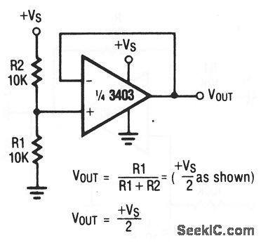
This circuit uses one section of a 3403 op amp as a voltage reference.Compare this basic circuit to the higher-precision circuit of Fig. (View)
View full Circuit Diagram | Comments | Reading(600)
Difference_amplifier
Published:2009/7/23 21:39:00 Author:Jessie
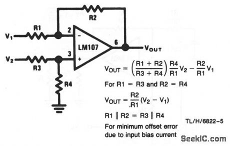
This circuit shows an LM107 that is connected in the classic difference-amplifier configuration, where VOUT depends on the difference between V1 and V2 as well as the ratios of R1 through R4. As shown, the calculations for VOUT are simplified when R1=R3 and R2= R4. (View)
View full Circuit Diagram | Comments | Reading(0)
DIRECT_COUPLED_PREAMP
Published:2009/7/6 1:52:00 Author:May
Provldes frequency response from 0 to 1 MHz at very low power levels, as required fordriving CMOS logic of frequency counter. Diodes protect input from overload. Output impedance of frequency source should be kept below 50K to minimize noise pickup.-R. Tenny, Counter Pre-Amp Matches CMOS Logic Capability, EDN Magazine, Sept. 20, 1976, p 114 and 116. (View)
View full Circuit Diagram | Comments | Reading(1584)
60_kHz_WWVB_PREAMP
Published:2009/7/6 1:43:00 Author:May
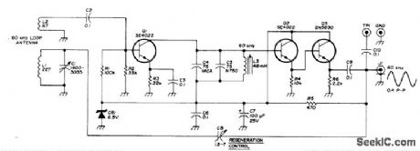


Installed in loop antenna to boost strength of 60-kHz standard-frequency broadcasts from NBS station at Boulder, Colorado, enough to drive digital frequency counter for which circuit is also given in article.Although construction details apply to double-copper shielded 54-inch,diameter circular loop, preamp can also be used with simple unshlelded wood-frame loop. Output coax supplies regulated 10 VDC for preamp, Article indudes techniques for minimizing interference from nearby TV receivers.-H. Isenring,WWNB Signal Processor, Ham Badio, March 1976, p 28.-34.
(View)
View full Circuit Diagram | Comments | Reading(1897)
NO_COMPROMISE_PHONO_PREAMP
Published:2009/7/6 1:31:00 Author:May

Distortion figure is below 0.002 percent, overload margin is about 47 dB, and S/N ratio is 71 dB for phono amplifier. This feeds normalization amplifier whose output is set at 0 dBm by setting input gain control. Feedback components R2, R3, and C2 provide RIAA bass boost. Tone-control circuit is based on Baxandall system but has bass control turnover frequency which decreases as control approaches flat position. This allows small amount of boost at low end of audio spectrum to correct for transducer shortcomings. Article describes circuit operation in detail and gives additional circuits used for tape output, level detection, noise gate, and power supply. Transistors Tr1-Tr6 and Tr13-Tr15 are BCY71; Tr7-Tr9 and Tr16-Tr18 are MPS A06; Tr10-Tr12 and Tr19-Tr21 are MPS A56; Tr9 is BFX85 or equivalent. Circuit is duplicated for other stereo channel,-D. Self, Advanced Preamplifier Design, Wireless World, Nov. 1976, p 41-46. (View)
View full Circuit Diagram | Comments | Reading(1182)
O_3_MHz_PREAMP
Published:2009/7/6 1:31:00 Author:May
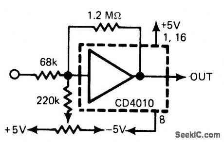
Provides wide frequency response required for amplifying 100 mV P-P input signals to 5-V level fordriving CMOS logic of frequency counter.-R. Tenny, Counter Pre-Amp Matches CMOS Logic Capability, EDN Allagazine, Sept. 20, 1976, p 114 and 116. (View)
View full Circuit Diagram | Comments | Reading(655)
PROFESSIONAL_AUDIO_NAB_TAPE_PLAYBACK_PREAMPLIFIER
Published:2009/7/6 1:31:00 Author:May
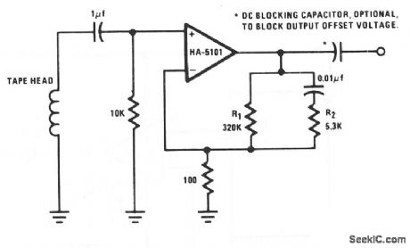
The preamplifier is configured to provide low-frequency boost to 50 Hz, flat response to 3 kHz, and high-frequency attenuation above 3 kHz. Compensation for variations in tape and tape head performance can be achieved by trimming R1 and R2.
(View)
View full Circuit Diagram | Comments | Reading(1862)
SPLIT_SUPPLY_PHONO_PREAMP
Published:2009/7/6 1:29:00 Author:May
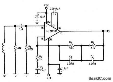
Low-noise circuit using LM1303 provides RIAA response and operates over supply voltage range of ±4.5 to ±15 V. 0-dB reference gain (1 kHz) is about 34 dB. Input is from magnetic cartridge.- Audio Handbook, National Semiconductor, Santa Clara, CA, 1977, p 2-25-2-31. (View)
View full Circuit Diagram | Comments | Reading(852)
RIAA_PREAMPLIFIER
Published:2009/7/6 1:28:00 Author:May

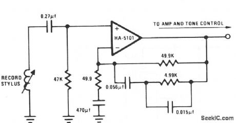
The circuit essentially provides low-frequency boost below 318 Hz and high-frequency attenuation above 3150 Hz. Recent modifications to the response standard include a 31.5-Hz peak gain region to reduce dc-oriented distortion from external vibration. (View)
View full Circuit Diagram | Comments | Reading(0)
EQUALIZED_PREAMP
Published:2009/7/6 1:28:00 Author:May

Low-frequency boost is provided by inductance of magnetic cartridge, acting with RC network to approximate theoretical RIAA or NAB compensation as deter-mined by position of compensation switch. Input resistor is selected to provide specified loading for cartridge. Output noise is about 0.8 m VRMS with input shorted.- Signetics Analog Data Manual, Signetics, Sunnyvale, CA, 1977, p 638-639. (View)
View full Circuit Diagram | Comments | Reading(621)
MAGNETIC_CARTRIDGE_PREAMP_1
Published:2009/7/6 1:27:00 Author:May
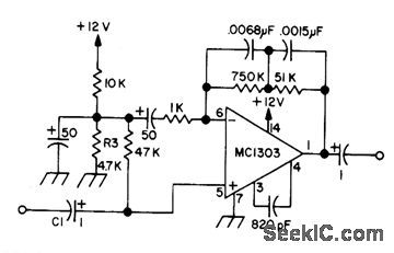
Uses dual opamp for stereo, other half of which is connected exactly the same but with connections to pin numbers changed to those in parentheses: 6(5), 5(8), 3(11), 4(10), and 1(13).-Circuits, 73 Magazine, Sept. 1973, p 143. (View)
View full Circuit Diagram | Comments | Reading(767)
INPUT_BUFFER_FOR_PREAMP
Published:2009/7/6 1:27:00 Author:May
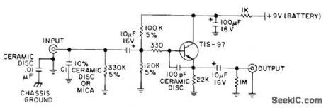
Used between cartridge and preamp of each stereo channel to make comparison testing of phonograph preamps more nearly independent of cartridge and cable capacitances. Buffer terminates cartridge in 47K in parallel with 01. Buffer can then serve as sonic reference for comparison with preamps for which input impedance is un known. Article tells how to determine correct value of C1 for cartridge used and covers preamp test procedures in detail.-T. Holman, New Tests for Preamplifiers, Audio, Feb. 1977, p 58, 60, 62, and 64. (View)
View full Circuit Diagram | Comments | Reading(703)
RIAA_PREAMP
Published:2009/7/6 1:26:00 Author:May
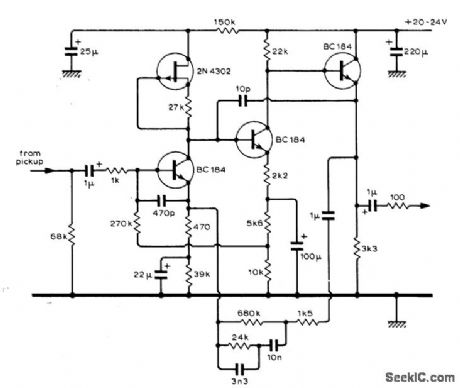
Low-noise circuit (below -70 dB referred to 5-mV input from pickup) has high overload capability and low distortion (below 0.05% intermodulation at 2 VRMS output}. Arrangement of first stage gives improved transient reponse over usual feedback pair. Second stage provides gain of 10.-S. F. Bywaters, RIAA-Equalized Pre-Amplifier, Wireless World, Dec. 1974, p 503. (View)
View full Circuit Diagram | Comments | Reading(1220)
STEREO_MAGNETIC_PICKUP_PREAMP
Published:2009/7/6 1:23:00 Author:May
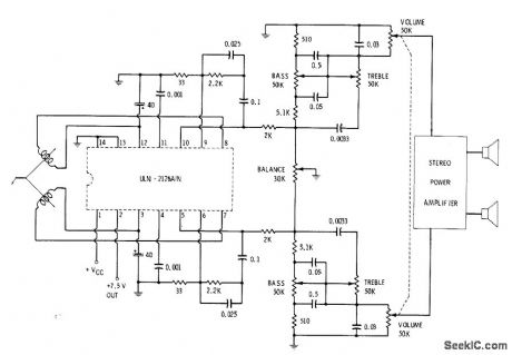
Single Sprague ULN-2126A IC accepts low impedance of magnetic cartridge and provides up to 2-W output power for driving commercial stereo power amplifier. Circuit includes balance control and all tone controls along with ganged volume control. Values shown give proper equalizatioan for playback of records.-E. M. Noll, “Linear IC Principles, Experiments, and Projects,” Howard W. Sams, Indianapolis, IN, 1974, p 237 and 242. (View)
View full Circuit Diagram | Comments | Reading(766)
MAGNETIC_CARTRIDGE_PREAMP
Published:2009/7/6 1:22:00 Author:May
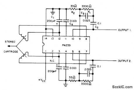
Uses Signetics PA239 dual low-noise amplifier designed specifically for low-level low-noise applications. Stereo channel separation at 1 kHz is typically 90 dB, and total harmonic distortion without feedback is 0.5%. Circuit matches amplifier response with RIAA recording characteristic. Supply voltage can be between 9 and 15 V at 22 mA. Article gives design equations.-A. G. Ogilvie, Construct a Magnetic-Cartridge Preamp, Audio, June 1974, p 40 and 42. (View)
View full Circuit Diagram | Comments | Reading(871)
Lighting (Contd.) Circuit Principle Diagram of Liberation CA6440 Series Light Buses
Published:2011/7/20 0:10:00 Author:Michel | Keyword: Light Buses, Lighting (Contd.) Circuit, Principle Diagram
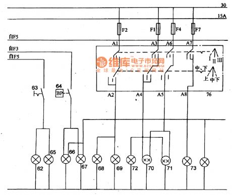
62-fog lamp,63-switch of fog lamp,64-brake light switch 65 and 66一brake light 67-tail light,68 and 69- headlamp (high beam),70 and 71-headlamp(distance light),72-indicator of distance light 74- front signal light,75-instrument light,76-lighting switch. (View)
View full Circuit Diagram | Comments | Reading(489)
| Pages:119/250 At 20101102103104105106107108109110111112113114115116117118119120Under 20 |
Circuit Categories
power supply circuit
Amplifier Circuit
Basic Circuit
LED and Light Circuit
Sensor Circuit
Signal Processing
Electrical Equipment Circuit
Control Circuit
Remote Control Circuit
A/D-D/A Converter Circuit
Audio Circuit
Measuring and Test Circuit
Communication Circuit
Computer-Related Circuit
555 Circuit
Automotive Circuit
Repairing Circuit